Keyestudio Raspberry Pi Pico 42 in 1 Sensor Kit
1.Description
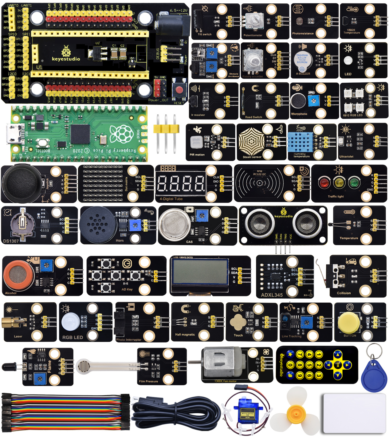
The Keyestudio Raspberry Pi Pico 42 in 1 sensor kit mainly contains 37 commonly used sensors/modules, a Raspberry Pi Pico board, a Raspberry Pi Pico expansion board and Dupont wires.
The 42 sensors and modules are fully compatible with the Raspberry Pi Pico shield. You only need to stack the Raspberry Pi Pico board onto the Raspberry Pi Pico shield, and hook up them with Dupont wires, which is simple and convenient.
To make you master the electronic knowledge, detailed tutorials (Micropython), schematic diagrams, wiring methods and test code are included. Through these projects, you will have a better understanding about programming, logic and electronics.
2.Kit
# |
Picture |
Name |
QTY |
|---|---|---|---|
1 |
|
Keyestudio Purple LED Module |
1 |
2 |
|
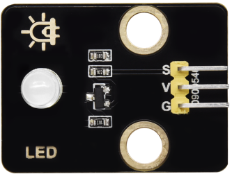
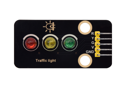
Keyestudio Common Cathode RGB Module |
1 |
3 |
|
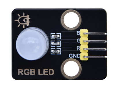
Keyestudio Traffic Lights Module |
1 |
4 |
|
Keyestudio Active Buzzer |
1 |
5 |
|
Keyestudio 8002b Audio Power Amplifier |
1 |
6 |
|
Keyestudio Button Module |
1 |
7 |
|
Keyestudio Tilt Sensor |
1 |
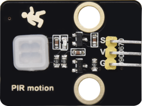
8 |
|
Keyestudio PIR Motion Sensor |
1 |
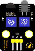
9 |
|
Keyestudio Obstacle Avoidance Sensor |
1 |
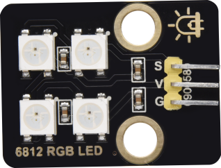
10 |
|
Keyestudio 6812 RGB Module |
1 |
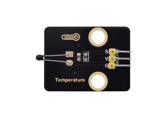
11 |
|
Keyestudio NTC-MF52AT Thermistor |
1 |
12 |
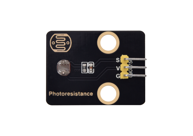
|
Keyestudio Photoresistor |
1 |
13 |
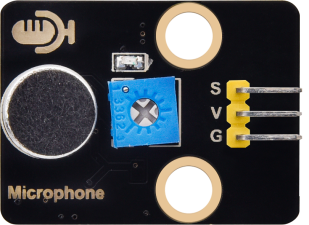
|
Keyestudio Sound Sensor |
1 |
14 |
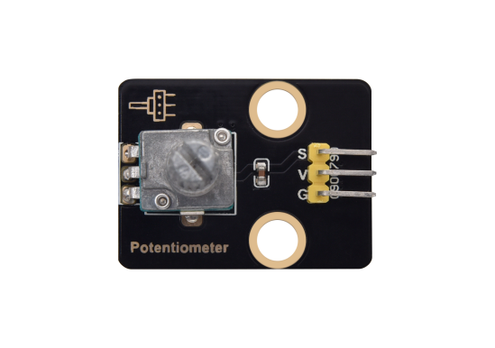
|
KeyestudioRotary Potentiometer |
1 |
15 |
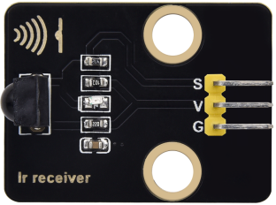
|
Keyestudio IR Receiver |
1 |
16 |
|
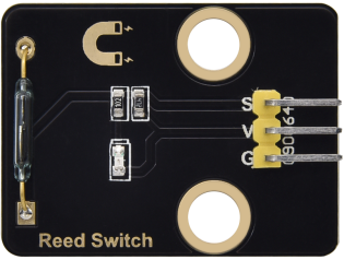
Keyestudio Reed Switch Sensor |
1 |
17 |
|
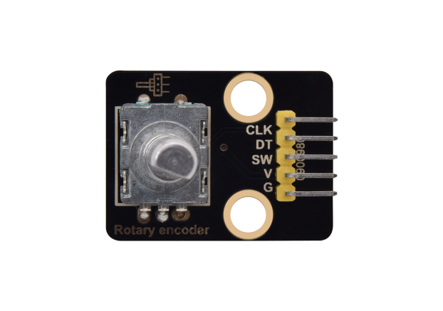
Keyestudio Rotary Encoder Module |
1 |
18 |
|
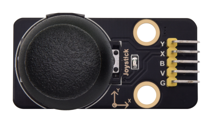
Keyestudio Joystick Module |
1 |
19 |
|
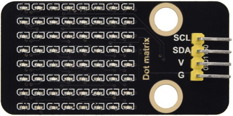
Keyestudio HT16K33 8X8 Dot Matrix Module |
1 |
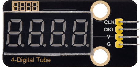
20 |
|
Keyestudio TM1650 4-Digit Tube Display |
1 |
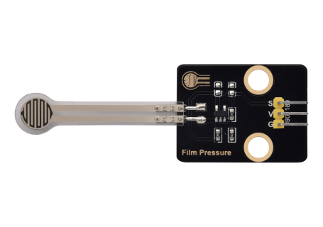
21 |
|
Keyestudio Thin-film Pressure Sensor |
1 |
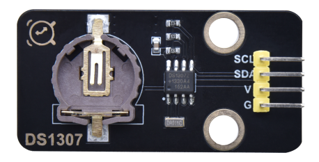
22 |
|
Keyestudio DS1307 Clock Sensor |
1 |
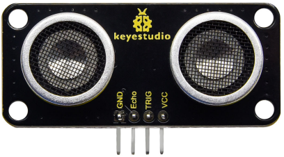
23 |
|
Keyestudio SR01 Ultrasonic Sensor |
1 |
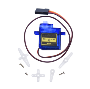
24 |
|
9G 90° Servo |
1 |
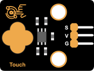
25 |
|
Keyestudio Capacitive Sensor |
1 |
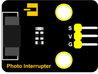
26 |
|
Keyestudio Photo Interrupter |
1 |
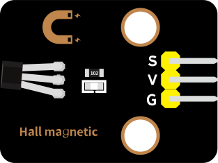
27 |
|
Keyestudio Hall Sensor |
1 |
28 |
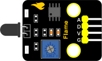
|
Keyestudio Flame Sensor |
1 |
29 |
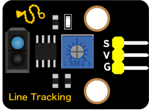
|
Keyestudio line Tracking Sensor |
1 |
30 |
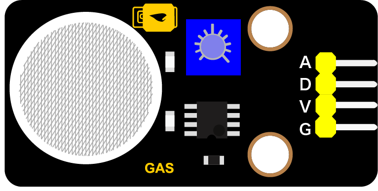
|
Keyestudio Analog Gas Sensor |
1 |
31 |
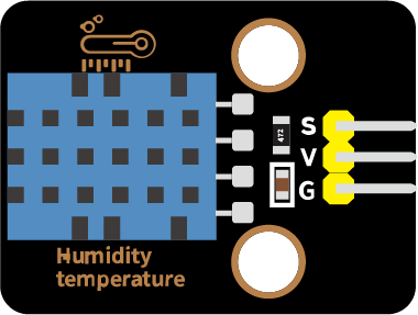
|
Keyestudio XHT11 Temperature and Humidity Sensor |
1 |
32 |
|
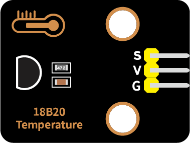
Keyestudio 18B20 Temperature Sensor |
1 |
33 |
|
keyestudio 130 Motor |
1 |
34 |
|
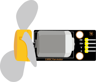
Fan |
1 |
35 |
|
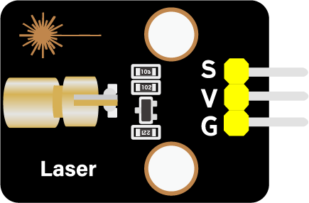
Keyestudio Laser Module |
1 |
36 |
|
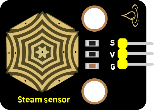
Keyestudio Steam Sensor |
1 |
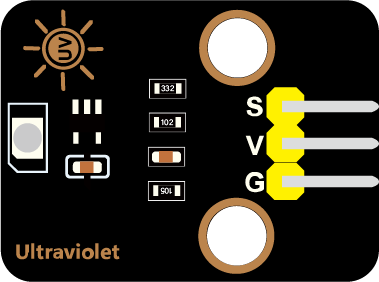
37 |
|
Keyestudio Ultraviolet Sensor |
1 |
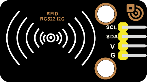
38 |
|
Keyestudio RFID Module |
1 |
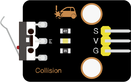
39 |
|
Keyestudio Collision Sensor |
1 |
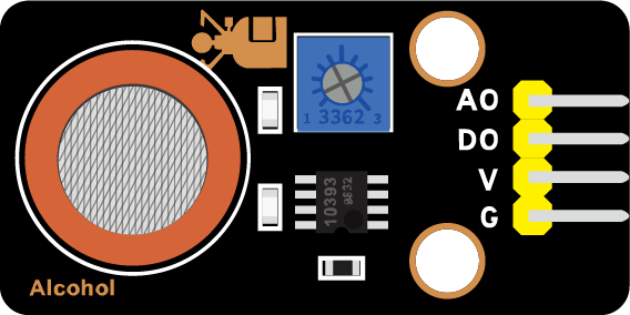
40 |
|
Keyestudio Alcohol Sensor |
1 |
41 |
|
Kyestudio LCD_128X32_DOT Module |
1 |
42 |
|
5-Channel AD Button Module |
1 |
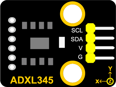
43 |
|
DXL345 Acceleration Module |
1 |
44 |
|
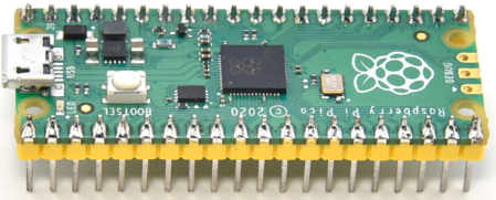
Raspberry Pi Pico Board |
1 |
45 |
|
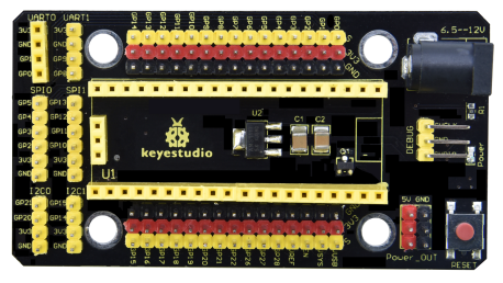
Keyestudio Raspberry Pico IO Expansion Board |
1 |
46 |
|
Keyestudio JMFP-4 17-Key Remote Control(without batteries) |
1 |
47 |
|
USB Cable |
1 |
48 |
|
F-F Dupont Wire |
1 |
49 |
|
White Card |
1 |
50 |
|
ABS RFID Key |
1 |


3.Preparations
3.1 Tools needed for the Raspberry Pi system
Hardware Tool:
Raspberry Pi 4B/3B/2B
Above 16G TFT Memory Card
Card Reader
Computer and other parts
3.1.1 Install Software Tools
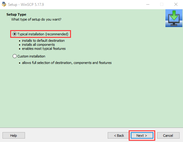
Windows System:
Putty
Download link: https://www.chiark.greenend.org.uk/~sgtatham/putty/
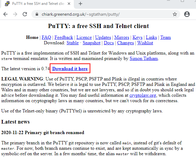
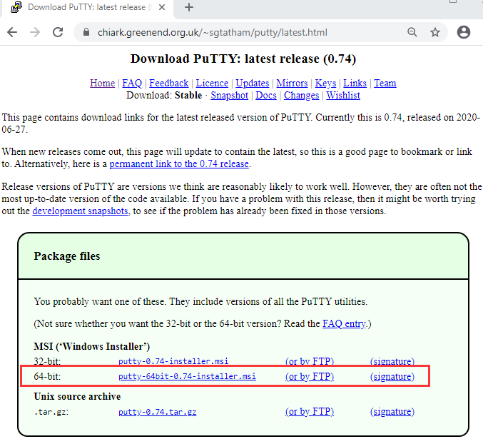
After downloading the package file  , double-click it and tap “Next”.
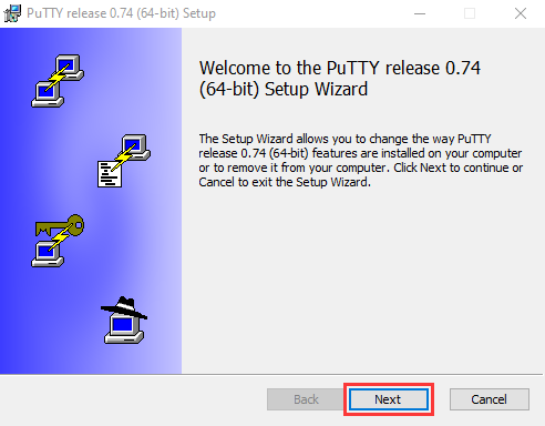
Click “Next”.
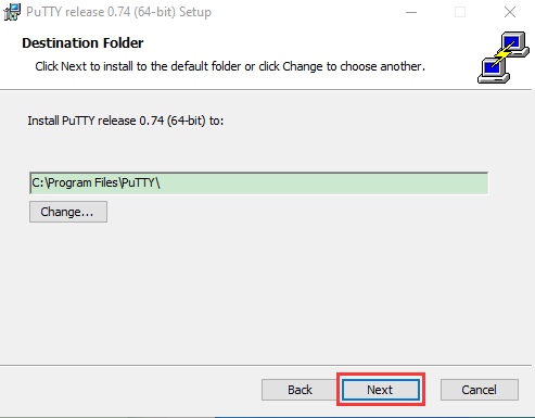
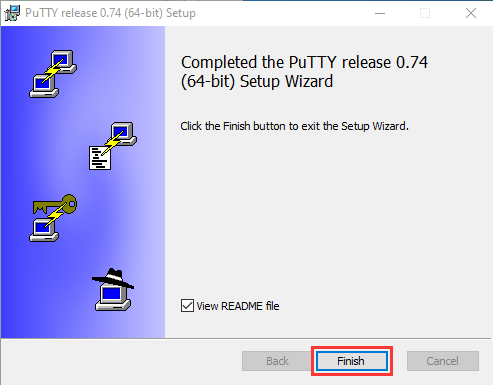
Choose “Install PuTTY files” and click “Install”.
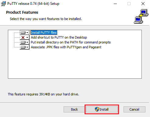
After a few seconds, click “Finish”.
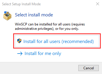
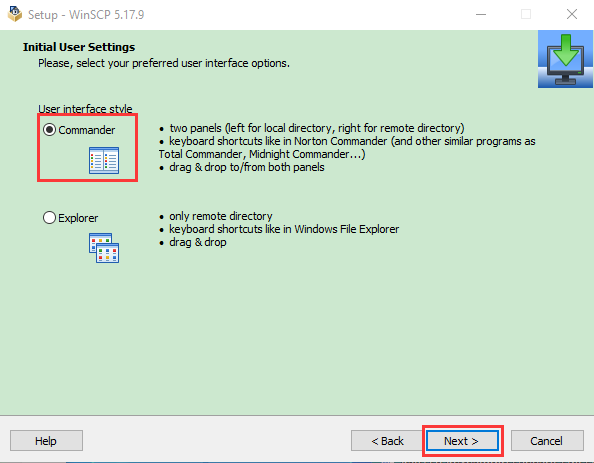
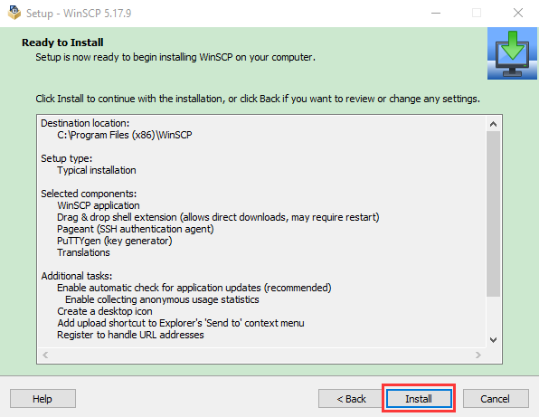
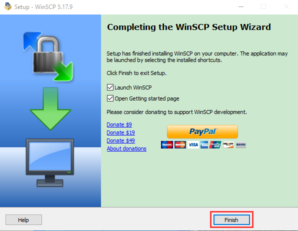
SSH Remote Login software -WinSCP
Link: https://winscp.net/eng/download.php
After downloading the package file , click
  .
.
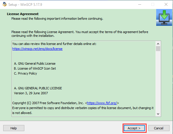
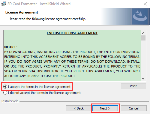
Click “Accept”.
Download link: http://www.canadiancontent.net/tech/download/SD_Card_Formatter.html
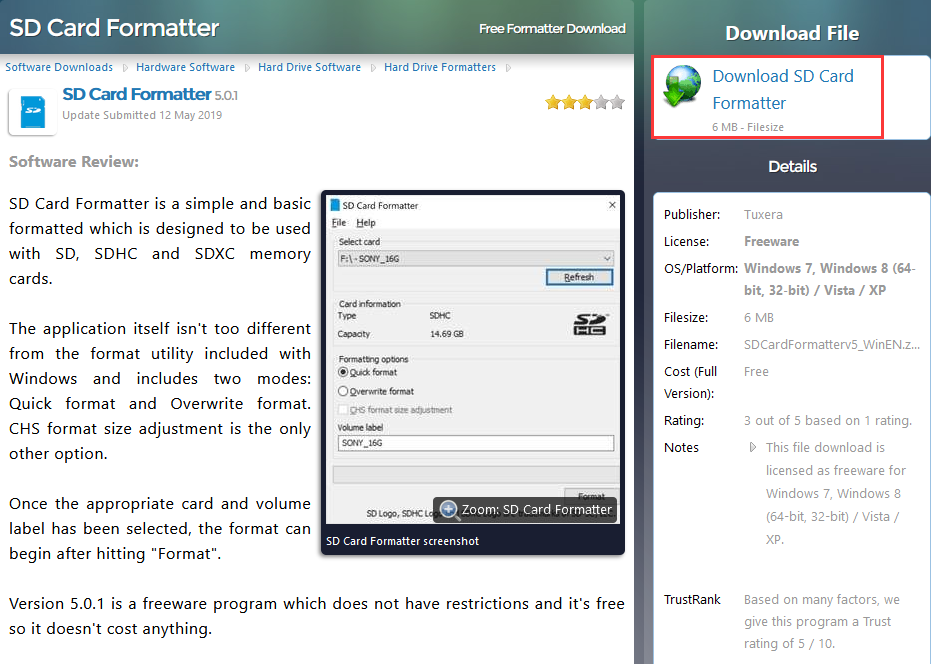

Unzip the SDCardFormatterv5_WinEN package, double-click  to run it.
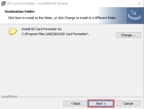
Click “Next” and choose  , then tap “Next”.
Click “Next” and “Install”.
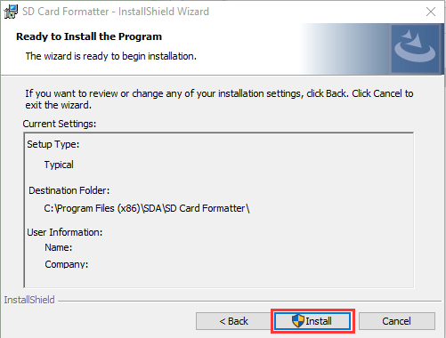
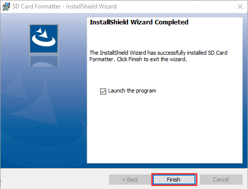
After a few seconds, click “Finish”.
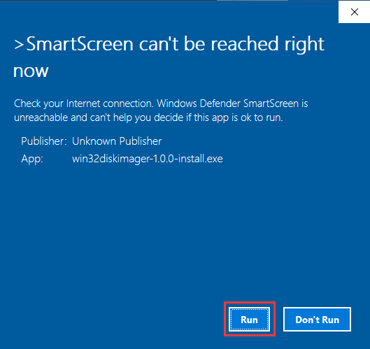
Win32 Disk Imager
Download link: https://sourceforge.net/projects/win32diskimager/

a. After the download, double-click and tap “Run”.
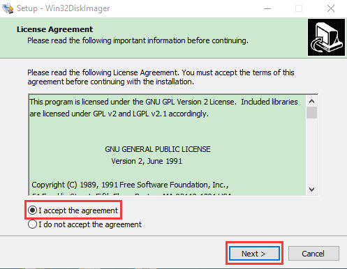
b. Select  and click “Next”.
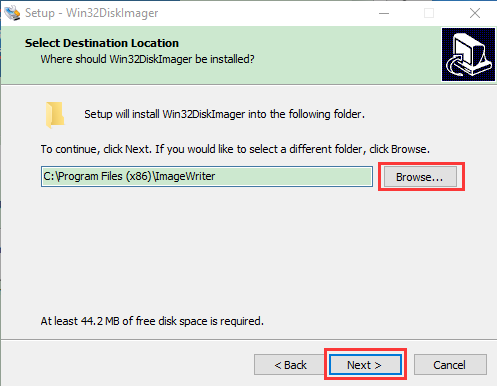
c. Click “Browse…” and find out the folder where the Win32 Disk Imager is located, tap“Next”.
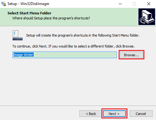
d. Tick  and click “Next” and “Install”.
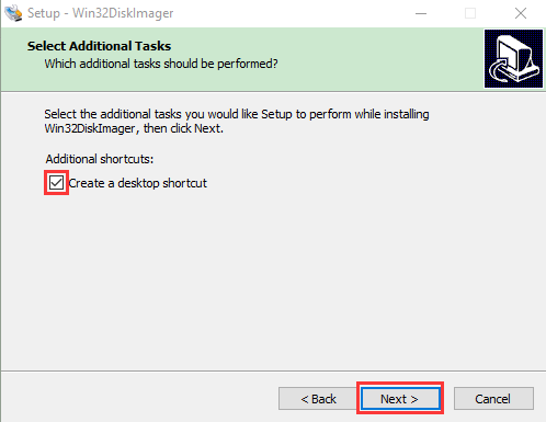
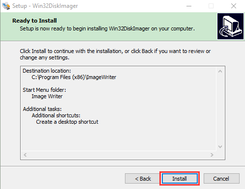
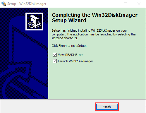
e. Click “Finish” after the installation is complete.
WNetWatcher
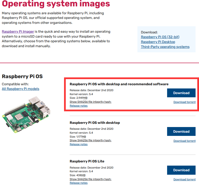
3.1.2 Raspberry Pi Imager
Download link for the latest version:
https://www.raspberrypi.org/downloads/raspberry-pi-os/
Old version:
Raspbian full:https://downloads.raspberrypi.org/raspbian_full/images/
Raspbian lite:https://downloads.raspberrypi.org/raspbian_lite/images/
We use the 2020.08.20 version in the tutorial and recommend you to use this version.
(Please download this version as shown in the picture below.)
3.2 Install Raspberry Pi OS on Raspberry Pi
Interface the TFT memory card with a card reader, then plug the card reader into a computer’s USB port.
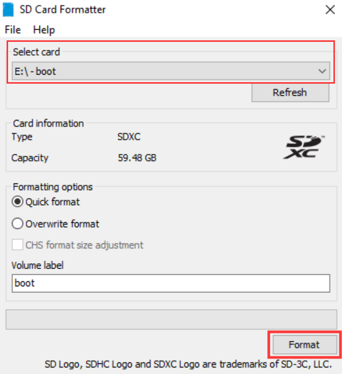
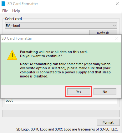
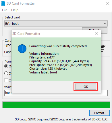
Use the SD Card Formatter to format a TFT memory card, as illustrated below.
(1) Burn system
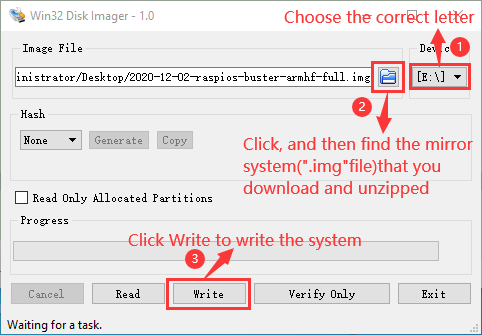
Burn the Raspberry Pi OS to the TFT memory card using Win32 Disk Imager software.
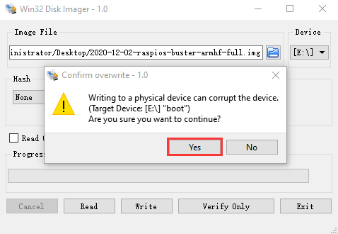
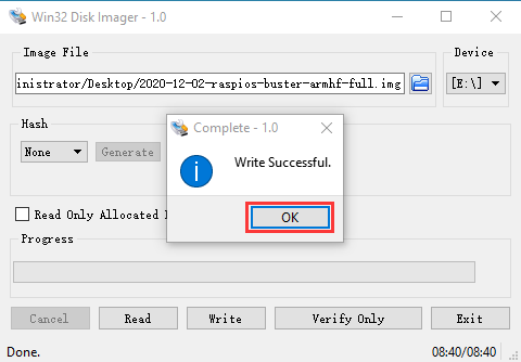
Don’t eject card reader after burning mirror system, build a file named SSH, then delete .txt.
The SSH login function can be activated by copying SSH file to boot category, as shown below.
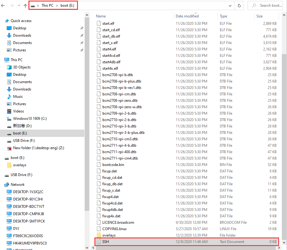
Eject card reader.
(2) Log in system
(Raspberry and PC should be in the same local area network.)
Insert TFT memory card into Raspberry Pi, connect internet cable and plug in power. If you have screen and HDMI cable of Raspberry Pi, you could view Raspberry Pi OS activating. If not, you can enter the desktop of Raspberry Pi via SSH remote login software—WinSCP and xrdp.
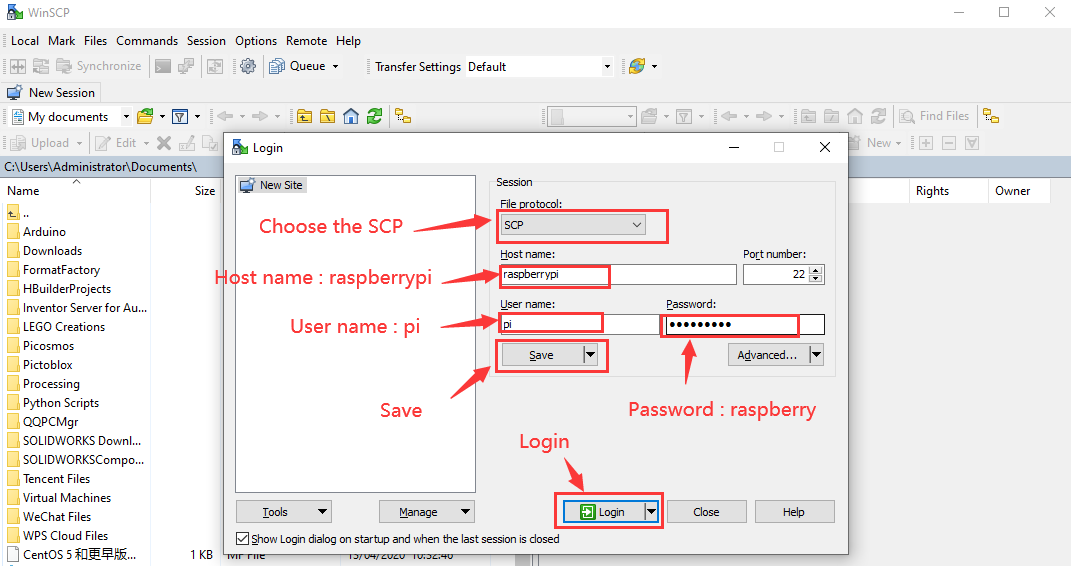
(3) Remote login
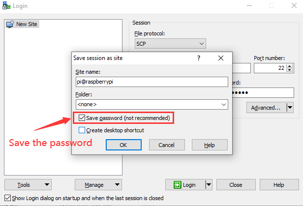
Enter default user name, password and host name on WinSCP to log in. Only a Raspberry Pi is connected in same network.
(4) Check IP and mac address
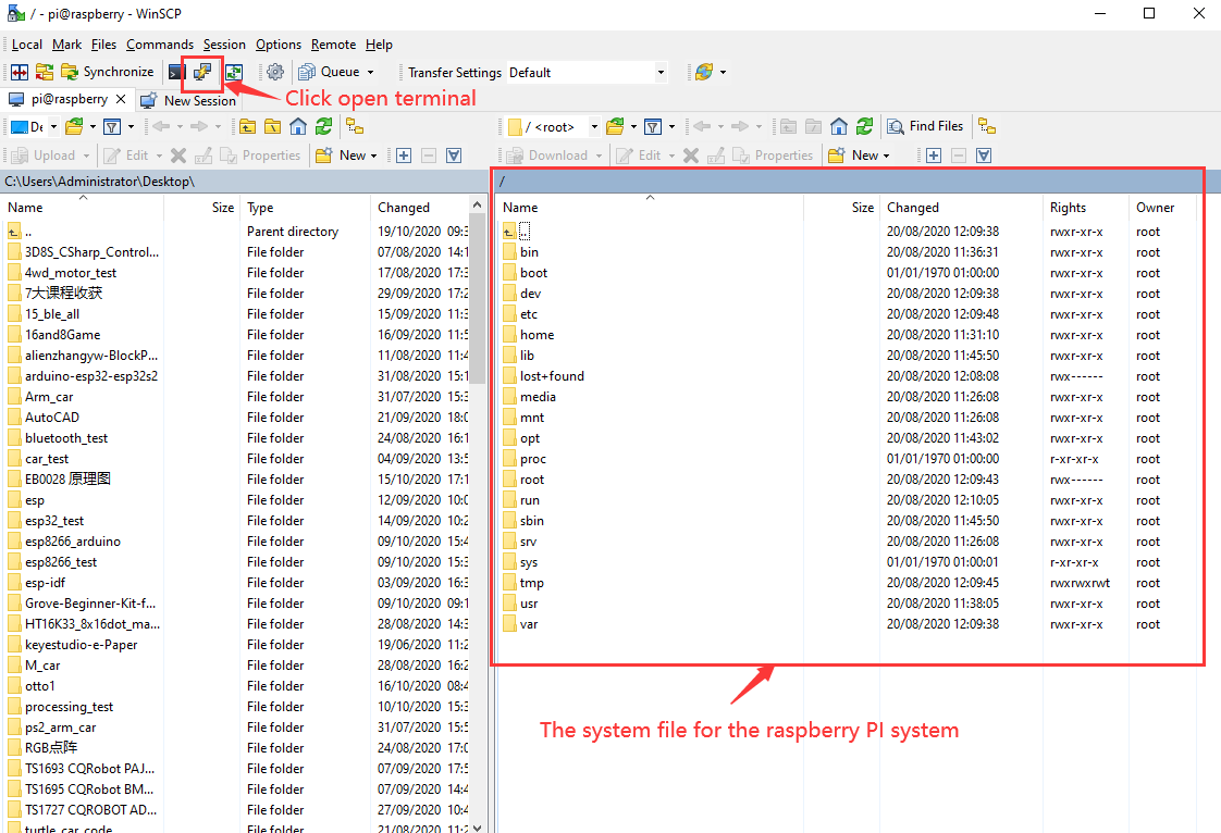
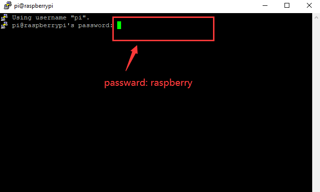
Click to open terminal and input the password: raspberry, and press “Enter” on keyboard.
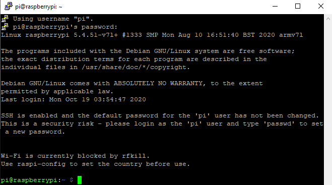
Logging in successfully, open the terminal, input ip a and tap “Enter” to check IP and mac address.
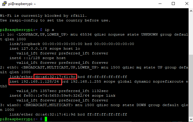
From the above figure, mac address of this Raspberry Pi is dc:a6:32:17:61:9c, and IP address is 192.168.1.128(use IP address to finish xrdp remote login).
Since mac address never changes, you could confirm IP via mac address when not sure which IP it is.
(5) Fix IP address of Raspberry Pi
IP address is changeable, therefore, we need to make IP address fixed for convenient use.
Follow the below steps:
Switch to root user
If without root user’s password
① Set root password
Input password in the terminal: sudo passwd root to set password.
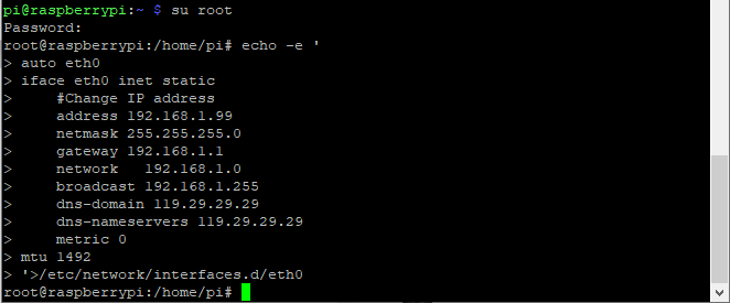
② Switch to root user
su root
③ Fix the configuration file of IP address
Firstly change IP address of the following configuration file.
(#New IP address: address 192.168.1.99)
Copy the above new address to terminal and press“Enter”.
Configuration File:
echo -e ‘
auto eth0
iface eth0 inet static
#Change IP address
address 192.168.1.99
netmask 255.255.255.0
gateway 192.168.1.1
network 192.168.1.0
broadcast 192.168.1.255
dns-domain 119.29.29.29
dns-nameservers 119.29.29.29
metric 0
mtu 1492
‘>/etc/network/interfaces.d/eth0
④ Reboot the system to activate the configuration file.
Input the restart command in the terminal: sudo reboot
You could log in via fixed IP afterwards.
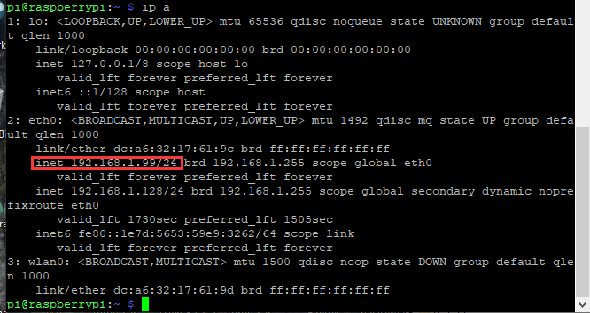
⑤ Check IP and insure IP address fixed well.
(6) Log in desktop on Raspberry Pi wirelessly
In fact, we can log in desktop on Raspberry Pi wirelessly even without screen and HDMI cable.
VNC and Xrdp are commonly used to log in desktop of Raspberry Pi wirelessly. Let’s take example of Xrdp.
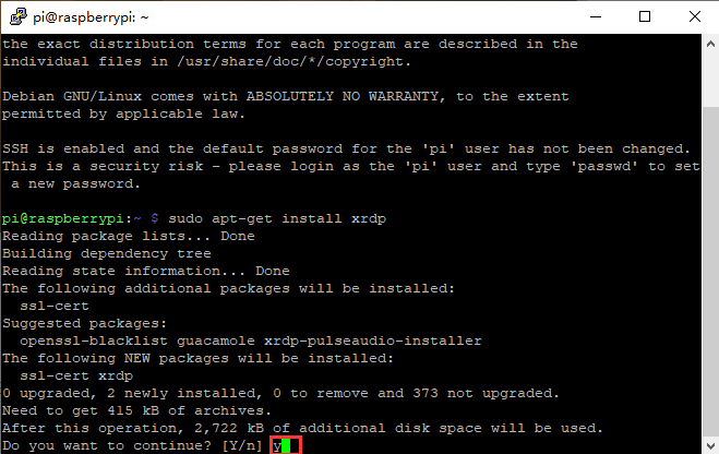
Install Xrdp Service in the terminal
Installation commands:
Switch to Root User: su root
Installation: apt-get install xrdp
Enter y and press “Enter”.
Open the remote desktop connection on Windows
Press WIN+R on keyboard and enter mstsc.exe.
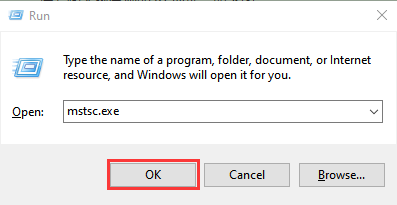
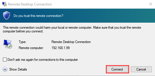
Input IP address of Raspberry Pi, as shown below.
Click “Connect” and tap “Connect”.
192.168.1.99 is IP address we use, you could change into your IP address.
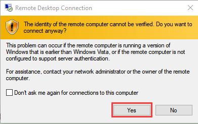
Click “Yes”.
Input user name: pi, default password: raspberry, as shown below.
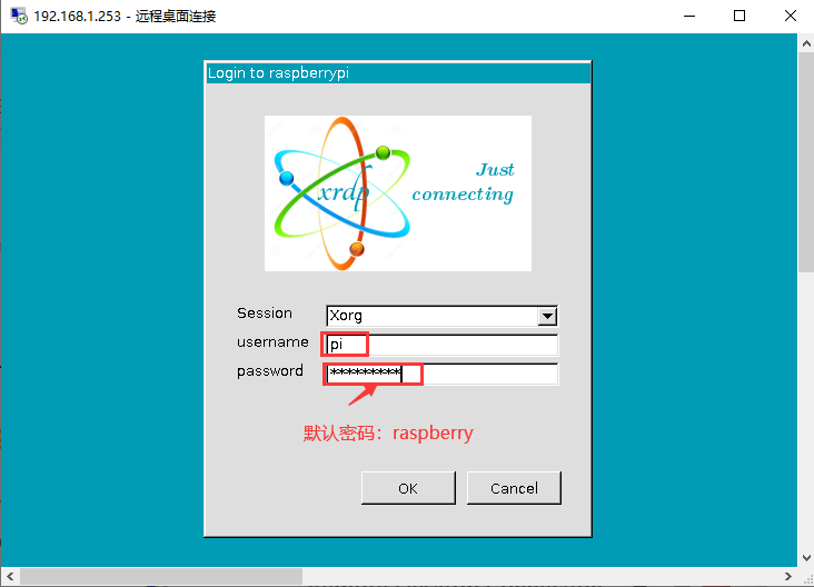
Click “OK” or “Enter”, you will view the desktop of Raspberry Pi OS, as shown below.

Now, we finish the basic configuration of Raspberry Pi OS.
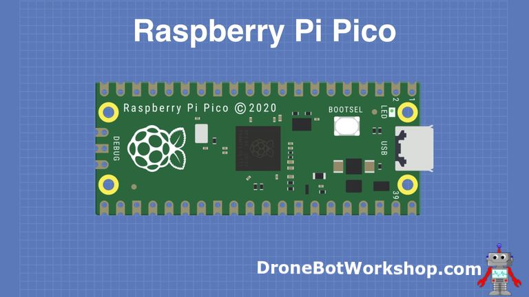
3.3 Raspberry Pi Pico

At the end of January 2021, the Raspberry Pi Foundation launched the Raspberry Pi Pico, which received a lot of attention due to its high-performance and low-cost.
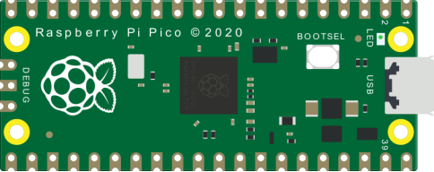
The size of Pico is 21mm × 51mm, which is similar to Arduino Nano’s.
Raspberry Pi Pico is a low-cost, high-performance microcontroller board with flexible digital interfaces. It integrates RP2040 microcontroller chip designed by Raspberry Pi, with dual-core Arm Cortex M0+ processor running up to 133 MHz, embedded 264KB of SRAM and 2MB of on-board Flash memory, as well as 26 multi-function GPIO pins. For software development, either Raspberry Pi’s C/C++ SDK, or the MicroPython is available. In this tutorial, we will use MicroPython.
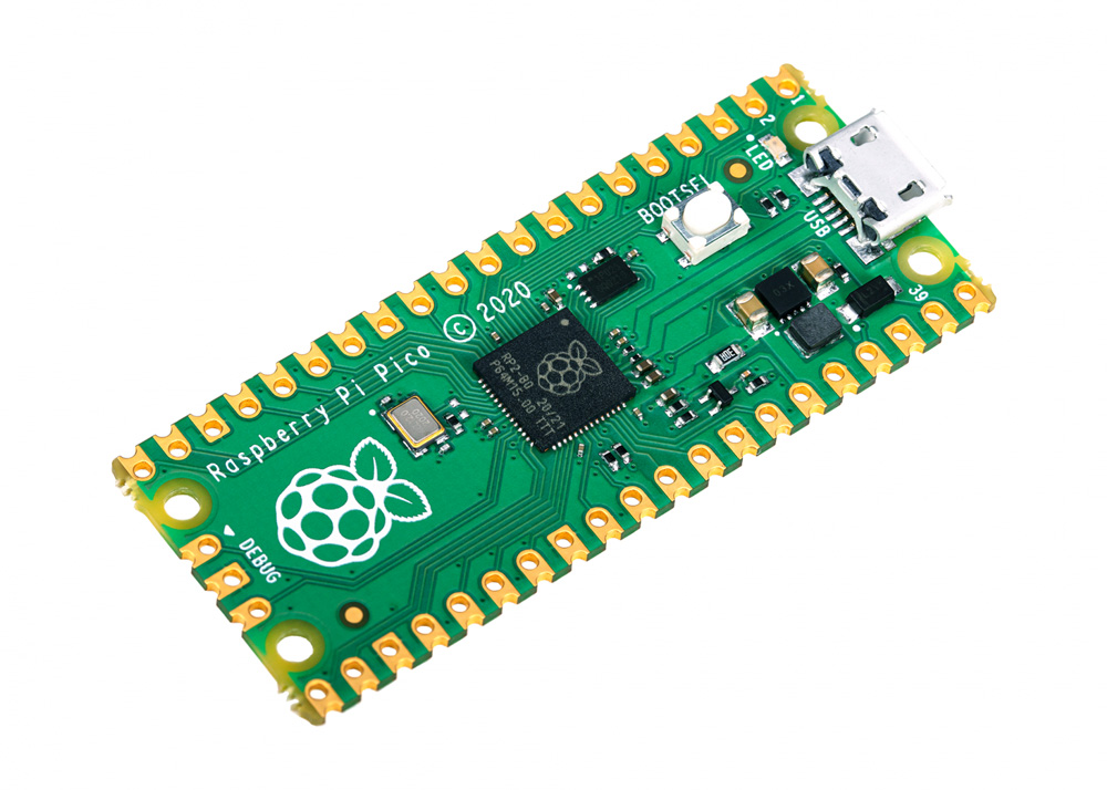
The bare board does not come with pins and you need to solder them yourself. This is a well-made board that can also be used as an SMD component and soldered directly to a printed circuit board.
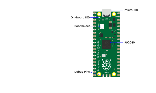
The most predominant feature on the board is the microUSB connector at one end. This is used both for communication and to supply power to the Pico. An on-board LED is mounted next to the microUSB connector, it is internally connected to GPIO pin 25. It’s worthwhile to note that this is the only LED on the entire Pico board.
The BOOTSEL pushbutton switch is mounted a bit down from the LED, it allows you to change the boot mode of the Pico so that you can load MicroPython onto it and perform drag-and-drop programming.
At the bottom of the board, you’ll see three connections, these are for a serial Debug option that we won’t be exploring here.
In the center of the board is the brains of the whole thing, the RP2040 MCU, which is capable of supporting up to 16MB of off-chip Flash memory, although in the Pico there is only 4MB.
Dual-core 32-bit Arm Cortex M0+ processor
Runs at 48MHz, but can be overclocked to 133MHz
30 GPIO pins(26 exposed)
Can support USB Host or Device mode
8 Programmable I/O(PIO) state machines
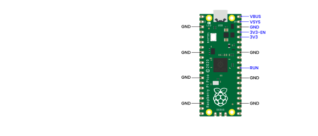
The Pico is a 3.3V logic device, however, it can be powered with a range of power supplies thanks to a built-in voltage converter and regulator.
GND: Ground connection. 8 grounding wires plus an additional one on the 3-pin Debug connector. They are square as opposed to rounded like the other connections.
VBUS: This is the power from the microUSB bus, 5V. If the Pico is not being powered by the microUSB connector then there will be no output here.
VSYS: This is the input voltage, which can range from 2 to 5V. The on-board voltage converter will change it to 3.3V for the Pico.
3V3: This is a 3.3V output from the Pico’s internal regulator. It can be used to power additional components, providing you keep the load under 300ma.
3V3_EN: You can use this input to disable the Pico’s internal voltage regulator, which will shut off the Pico and any components powered by it.
RUN: It can enable or disable the RP2040 microcontroller, it can also reset it.
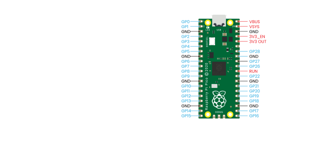
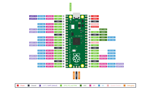
There are 26 exposed GPIO connections on the Raspberry Pi Pico board. They are laid out pretty-well in order, with a “gap” between GP22 and GP26 (those “missing” pins are used internally). All these pins have multiple functions, and you can configure up to 16 of them for PWM. There are two I2C buses, two UARTs, and two SPI buses, these can be configured to use a wide variety of GPIO pins.
The Pico has three Analog-to-Digital Converters, they are ADC0-GP26, ADC1-GP27, ADC2-GP28, and plus ADC-VREF converter used internally for an on-board temperature sensor. Note: The ADCs have a 12-bit resolution. However, the MicroPython has scaled the 12-bit resolution into a 16-bit resolution, which means that we will receive ADC values from 0 to 65535. The microcontroller’s working voltage is 3.3V, indicating that 0 corresponds to 0V and 65535 corresponds to 3.3V.
You can also provide an external precision voltage-reference on the ADC_VREF pin. One of the grounds, the ADC_GND on pin 33 is used as a ground point for that reference.
Raspberry Pi Pico Configuration |
|---|
Dual-core Arm Cortex-M0 + @ 133MHz |
2 × SPI, 2 × I2C, 2 × UART |
264KB of SRAM, and 2MB of on-board Flash memory |
16 PWM channels |
QSPI bus controller, supporting up to 16 MB of external Flash memory |
USB 1.1 with host and device support |
DMA controller |
8 × Programmable I/O (PIO) state machines for custom peripheral support |
30 GPIO pins, of which 4 can optionally be used as analog inputs |
Drag-and-drop programming using mass storage over USB |
Pinout Diagram:
Raspberry Pi did release a ton of technical documentation, plus a great guide called Get Started with MicroPython on Raspberry Pi Pico. It’s available in softcover, and as a PDF download as well. For more information, please refer to:
3.4 Using MicroPython
Preperation
MicroPython is a lean and efficient implementation of the Python 3 programming language that includes a small subset of the Python standard library and is optimized to run on microcontrollers and in constrained environments. MicroPython is packed full of advanced features such as an interactive prompt, arbitrary precision integers, closures, list comprehension, generators, exception handling and more. Yet it is compact enough to fit and run within just 256k of code space and 16k of RAM. MicroPython aims to be as compatible with normal Python as possible to allow you to transfer code with ease from the desktop to a microcontroller or embedded system.
For more information, please go to the official website: https://micropython.org
Programming the Pico:
You could use C/C++ or MicroPython. MicroPython is an interpreted language that is made specifically for microcontrollers. Many microcontroller users have familiarity with C/C++ as they are used on the Arduino and ESP32 boards. In this tutorial, we will use Thonny recommended by Raspberry Pi. Thonny bills itself as a“Python IDE for Beginners”, and it is available for Windows, Mac OSX and Linux. It was also part of the Raspberry Pi operating system(formerly Raspbian).
Boot and Install MicroPython:
The first thing that we need to do is to get MicroPython installed onto the Pico.
Download and burn firmware
Go to the official website to download the UF2 file:
https://www.raspberrypi.com/documentation/microcontrollers/#getting-started-with-micropython
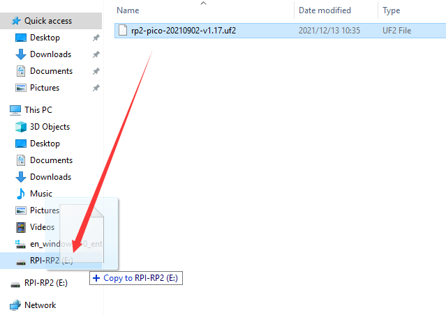
What I downloaded is . Once the download is complete, we proceed to burn the firmware.
With BOOTSEL held down, then plug the Pico into Raspberry Pi or your computer’s USB port.
Release it after the connection was finished. You should see a drive appearing on your computer with the name“RPI-RP2”.
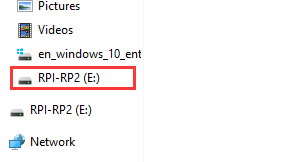
Move the UF2 file into “RPI-RP2”, and the Raspberry Pi Pico will automatically restart. At this point, the burning is complete.
Connect the Pico from a Raspberry Pi over USB
The MicroPython firmware is equipped with a virtual USB serial port which is accessed through the micro USB connector on Raspberry Pi Pico. Your computer should notice this serial port and list it as a character device, most likely /dev/ttyACM0.
You can run ls /dev/tty* to list your serial ports. There may be quite a few, but MicroPython’s USB serial will start with /dev/ttyACM. If in doubt, unplug the micro USB connector and see which one disappears. If you don’t see anything, you can try rebooting your Raspberry Pi.
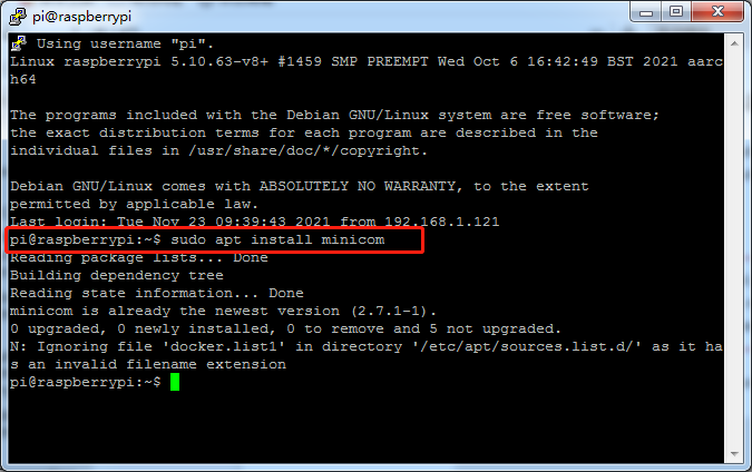
Enter the following command to install minicom:
sudo apt install minicom
open it as such:
minicom -o -D /dev/ttyACM0
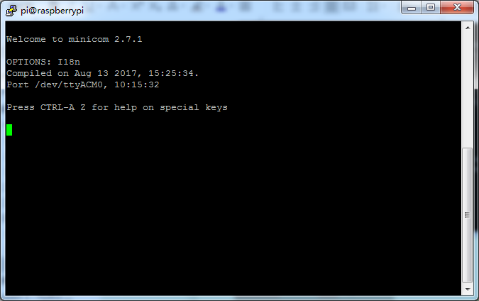
Press Ctrl + B.
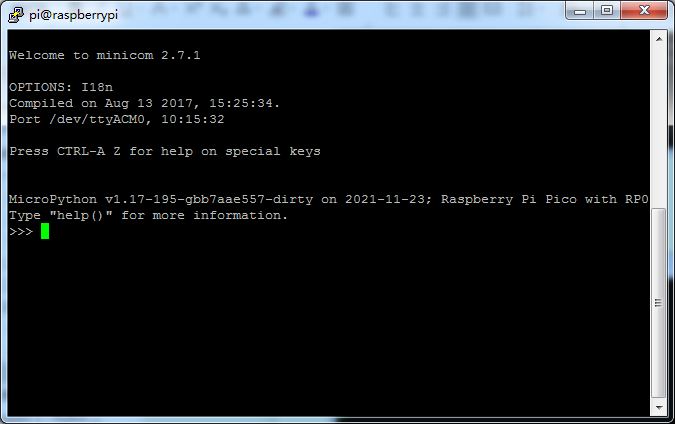
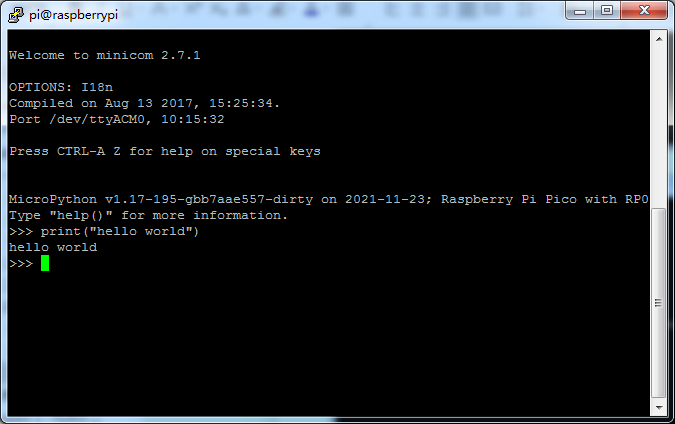
Enter print (“hello world”), it will show “hello world”.
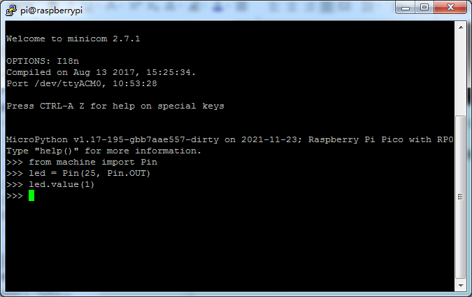
The on-board LED on Raspberry Pi Pico is connected to GPIO pin 25. The machine module is used to control on-chip hardware. This is standard on all MicroPython ports. Here we are using it to take control of a GPIO, so we can drive it high and low. If you type this in to light up the LED.
from machine import Pin
led = Pin(25, Pin.OUT)
led.value(1)
You can turn the LED off with:
led.value(0)
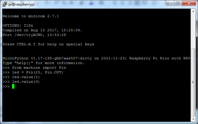
Now we have successfully connected the Pico from a Raspberry Pi over USB.
Install Thonny
The Raspberry Pi Imager that we downloaded comes with some commonly used software, and Thonny is among them.

If the Raspberry Pi Imager does not have Thonny, you need to manually download it yourself. Enter the following command in the terminal to download and install Thonny.
sudo apt install thonny
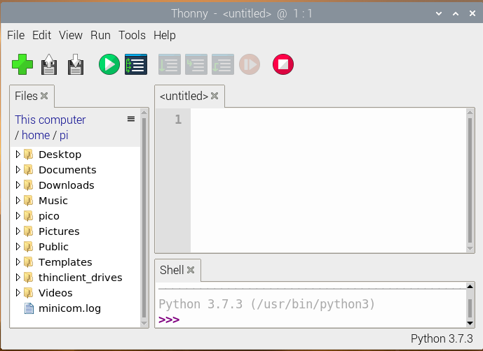
When opening Thonny for the first time select “Standard Mode” in the top right of the window. Open Thonny again, the interface is shown in the figure below.
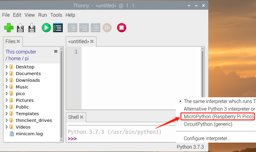
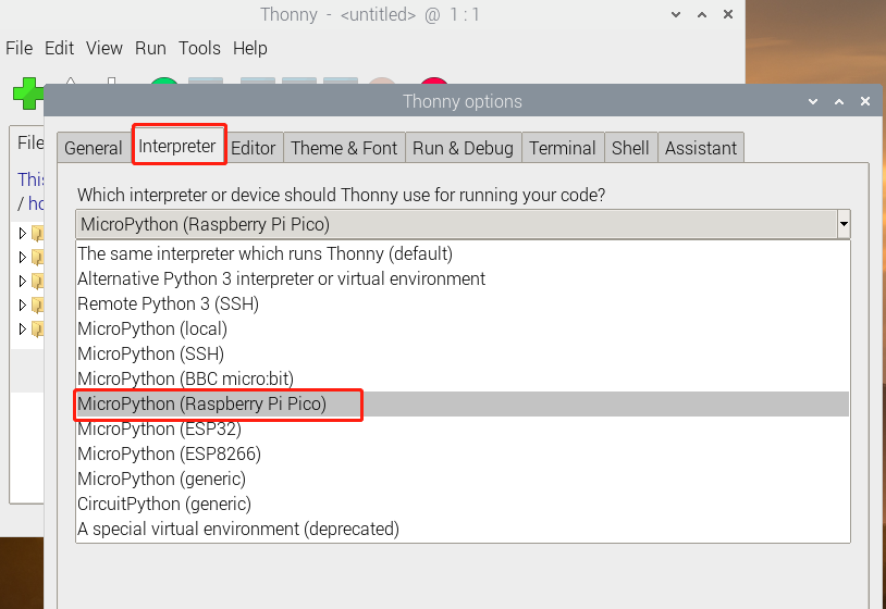
Select “MicroPython (Raspberry Pi Pico)” from the list, as shown below.
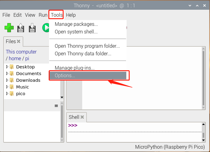
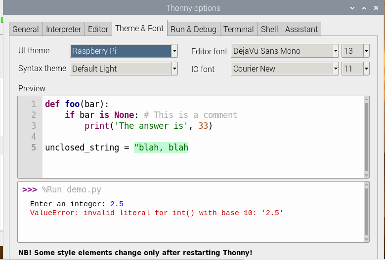
Click “Tools” and “Options”.
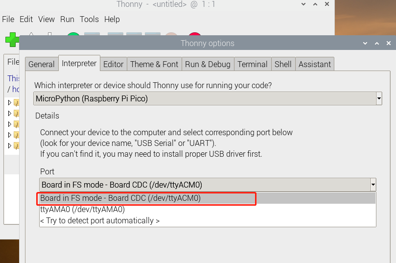
Select MicroPython(Raspberry Pi Pico) and the port as shown below.
Or select MicroPython (generic):
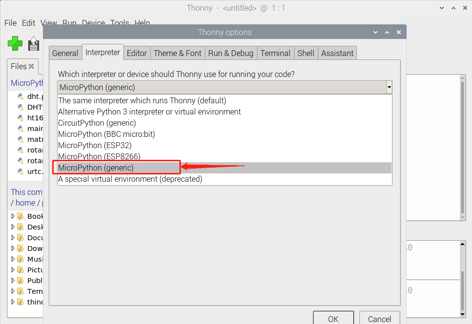
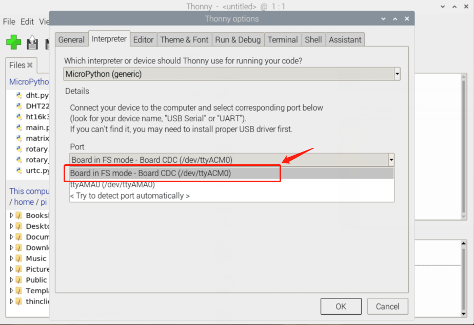
Click “Ok”.
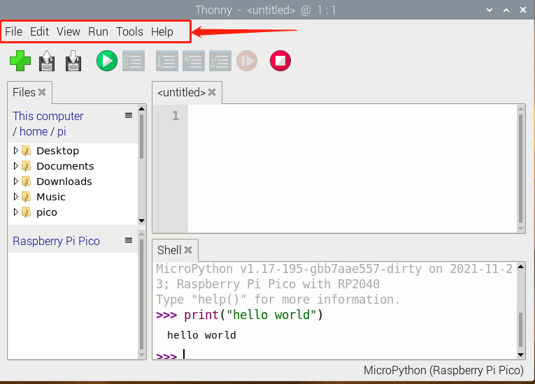
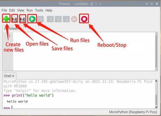
Thonny User Interface
Now we will introduce Thonny user interface. At the top is the main menu, there are “File”, “Edit”, “View”, “Run”, “Tools” and “Help”.
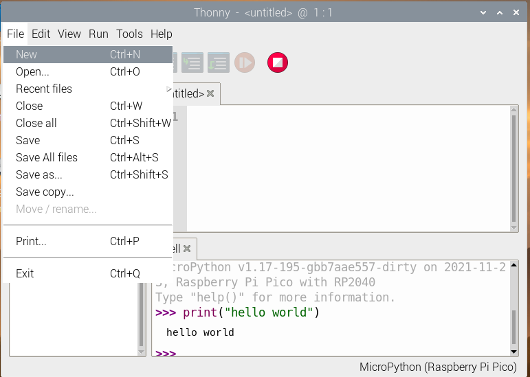
Click “File”, it shows some operations related to files.
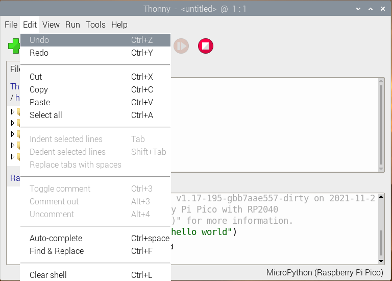
Click “Edit”, these are some options about code, such as copying, cutting, pasting.
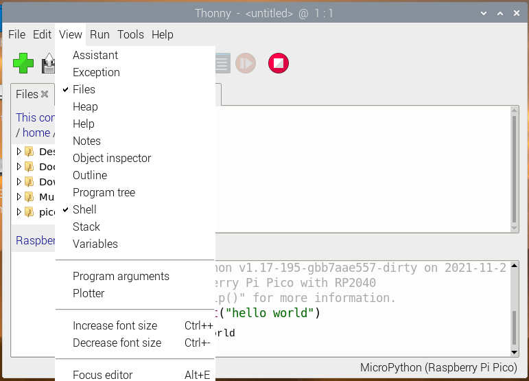
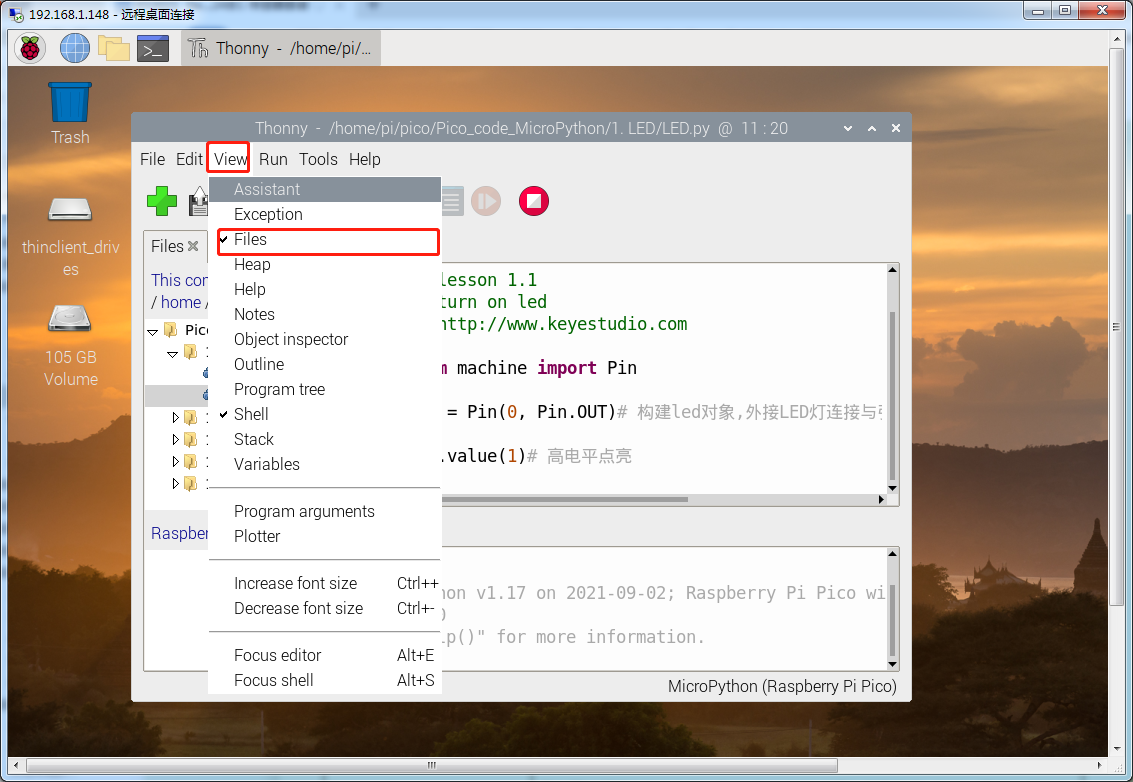
In the View drop-down menu, these are tools to assist you.
For example, if we do not tick Shell (the Shell is the“command line”of the Pico, and you can execute code directly here.), the result won’t be displayed.
Click “Files”, the files we saved will be shown on the left.
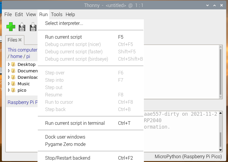
We can select interpreter in the Run drop-down menu, there are also some shortcuts used in programming.
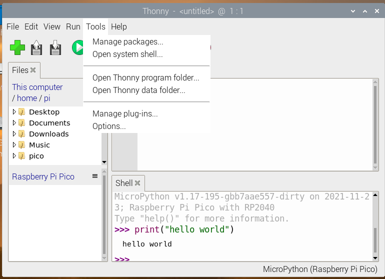
In Tools menu, we can select interpreter, font and import modules, etc.
In Help menu, we will see“Help contents”,“Version history”and more.
The icons below the main menu are our commonly used tool shortcuts.
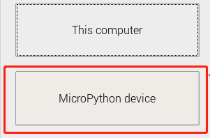
When we open or save files, it will shows the following contents.
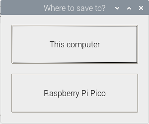
Note: if we select “MicroPython(generic)”, then “MicroPython Device” will be displayed.
We can open programs saved on the Raspberry Pi or the Pico, or save them on This computer or Raspberry Pi Pico.
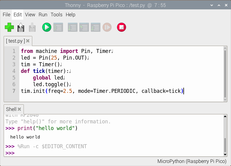
Copy the code below to the Thonny and save it to the Pico as test.py.
from machine import Pin, Timer
led = Pin(25, Pin.OUT)
tim = Timer()
def tick(timer):
    global led
    led.toggle()
tim.init(freq=2.5, mode=Timer.PERIODIC, callback=tick)
Click  to run the code, the on-board LED will blink, then click
  to stop, the LED won’t blink.
If we unplug the MicroUSB cable and plug it in again, the LED won’t blink after powering up. This is because we did not name the file main.py and save it to the Pico.
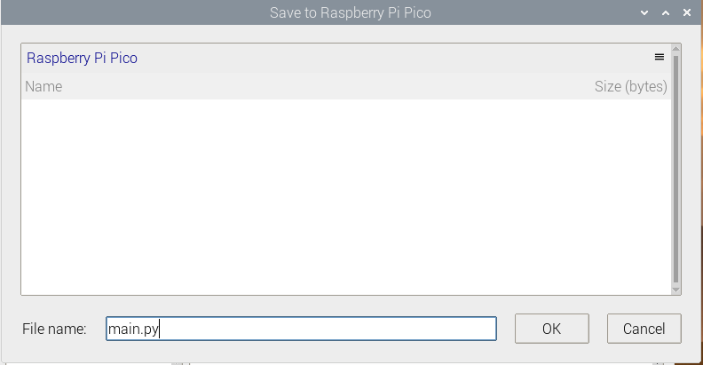
Click “File”, then click “Save as…” to choose Raspberry Pi Pico. After that, enter main.py as the file name (don’t forget to enter the .py file extension) and click “OK”. Run the code again, the LED will continue to blink.
When we unplug the cable again, then plug it in and power on, the LED will blink. This is because the Raspberry Pi Pico starts running the program saved on main.py after powering up.
Add Modules
Python is a powerful language due to its modules. Python scripting language with the most rich and powerful class library, enough to support the vast majority of day-to-day applications. By importing modules, this makes it easier for us when using some complex sensors.
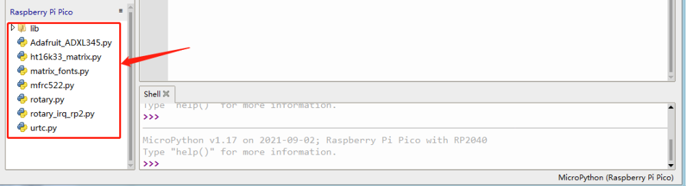
The method is simple, just save the module that we need to the Pico, or open the file saved on our computer, click“File” to choose “Save as”, then save it to the Pico board (right click the mouse, you can delete files). For instance, I saved some library files required for these courses on my Pico. Click“View”to choose“Files”, they will be displayed on the left of the interface.
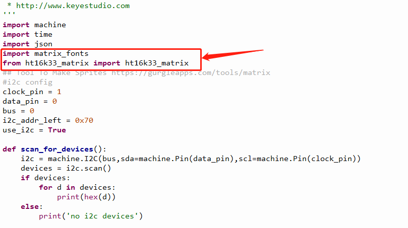
When using sensors, we can import the corresponding modules directly.
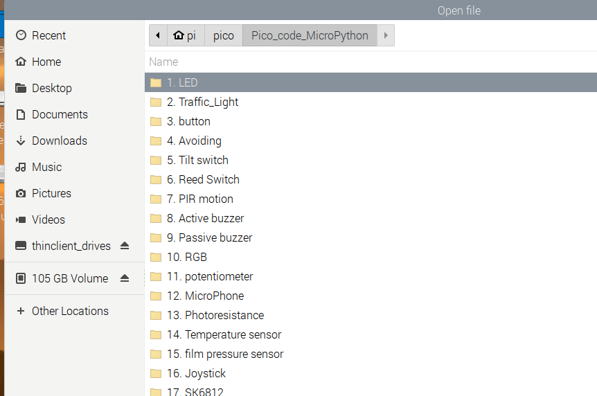
We save all the code in this tutorial to the Raspberry Pi. Open the terminal and create a folder in /home/pi.
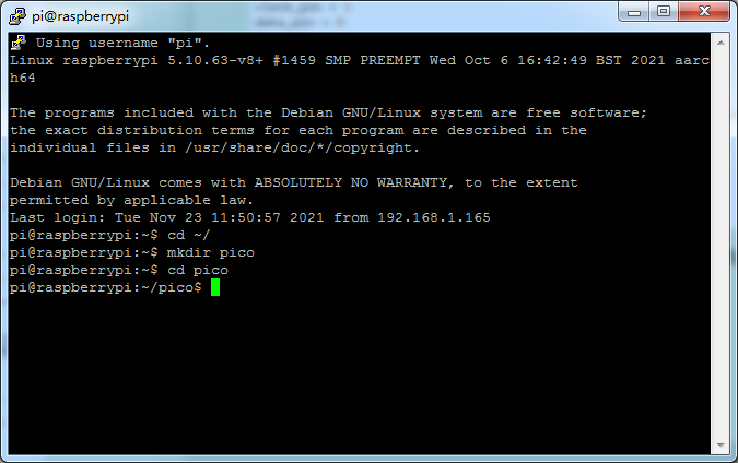
Copy the code to the folder and enter ls, it will show the following content.
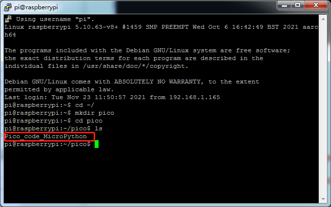
When using Thonny, we open this path to find the code we saved directly.
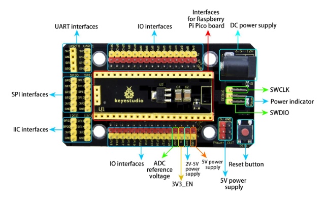
3.5 Keyestudio Raspberry Pico IO Shield
(1) Overview
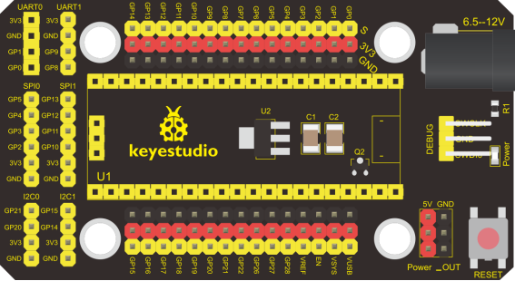
The Keyestudio Raspberry Pico IO shield is designed for Raspberry Pi Pico. No soldering required. To make the connection easier, the interfaces on the shield have silkscreen labels.The silkscreen labels of the 3pin interface generally are G, V, S. On the shield, G represents GND, V represents the VCC interface (3.3V), and S represents digital ports or analog ports. The pitch of the pin header on the shield is 2.54 mm. The sequence of the pin header is the same as the Pico board’s when wiring. The shield also comes with a reset button, a PWR power indicator and four holes.
The shield offers a variety of communication interfaces including I2C, UART, SPI, analog IO and digital IO, and provides an interface of power supply ranging from 6.5V to 12V.
(2) Specifications
Output current: ≦500mA
DC input voltage: 6.5 - 12V
Output voltage: DC 3.3V/5V
Ambient temperature(recommended): -10°C ~ 50°C
Dimensions: 45.339MM *83.617MM
Pin pitch: 2.54mm
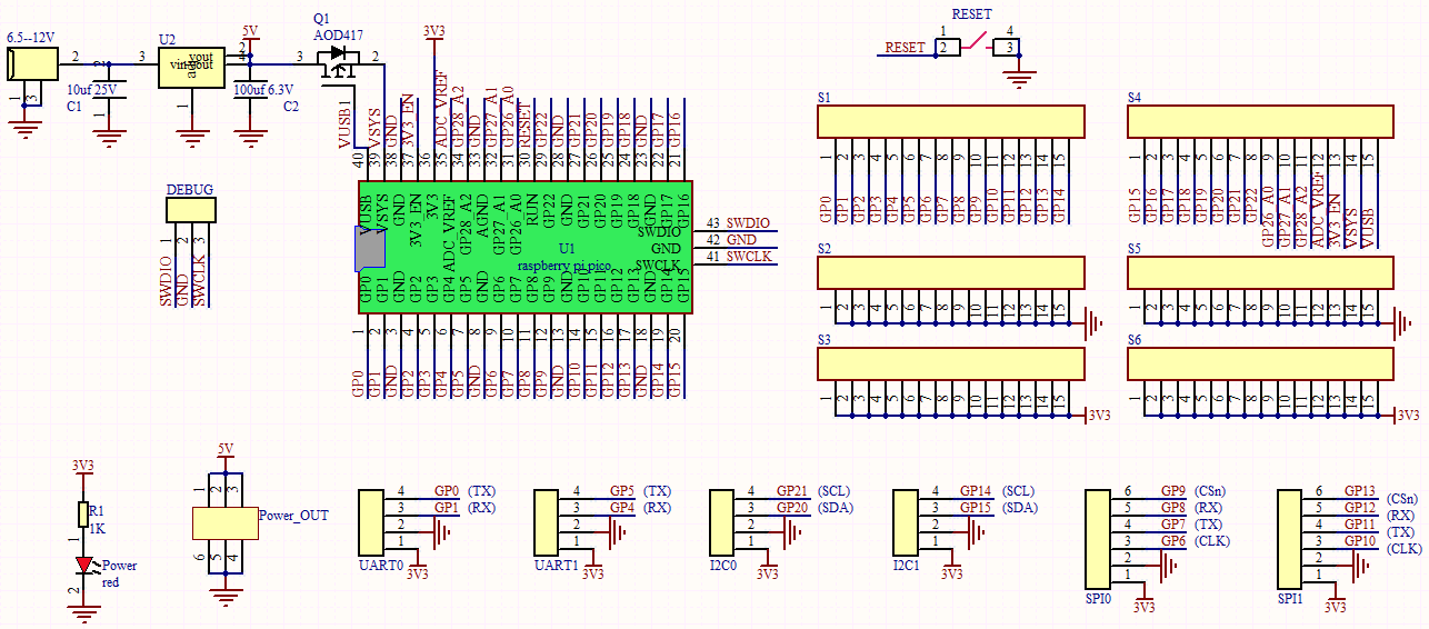
(3) Schematic diagram
(4) Pinout
(5) Connection
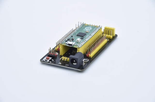
As shown below, stack the Raspberry Pi Pico board onto the Raspberry Pi Pico shield.
4. Projects
There are 37 sensors and modules in this kit. Next, we will analyze and introduce how they work step by step. Interface sensors with the Raspberry Pi Pico board and the Pico shield, run test codes and observe experimental phenomenon.
Note: please wire up components according to the given connection diagrams.
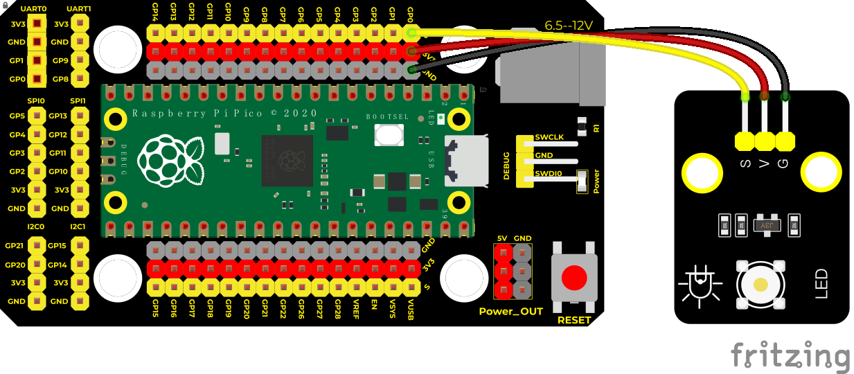
Project 1: Lighting up LED

Overview
In this project, we will make an experiment to light up the white LED module. The high and low levels can be controlled by programming, then the state of the LED can be controlled.
Working Principle
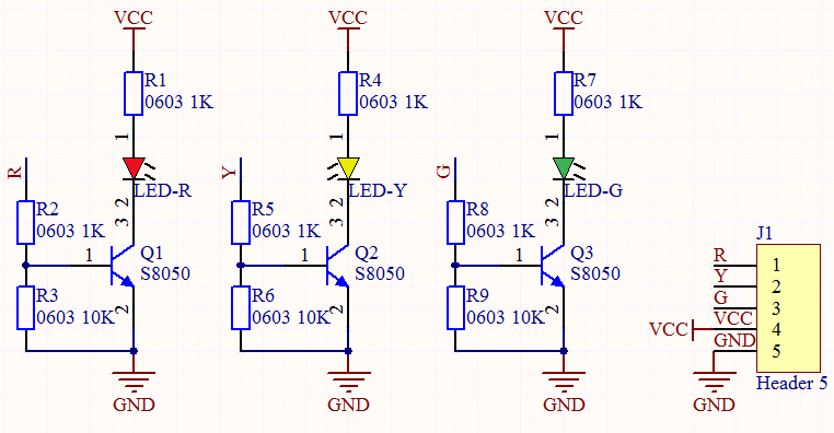
The two circuit diagrams are given. The left one is wrong wiring-up diagram. Why? Theoretically, when the S terminal outputs high levels, LED will receive the voltage and light up.
Due to limitation of IO ports of Pico board, weak current can’t make LED brighten.
The right one is correct wiring-up diagram. GND and VCC are powered up. When the S terminal is a high level, the triode Q1 will be connected and LED will light up (note: current passes through LED and R3 to reach GND by VCC not IO ports). Conversely, when the S terminal is a low level, the triode Q1 will be disconnected and LED will go off.
The triode Q1 is equal to a switch and R1 and R3 stand for limited resistors which can curb the size of current to prevent from burning out components.


Components
|
|
|
|---|---|---|
Raspberry Pi Pico Board*1 |
Raspberry Pi Pico Expansion Board*1 |
Keyestudio Purple LED Module*1 |
|
|
|
3P Dupont Wire*1 |
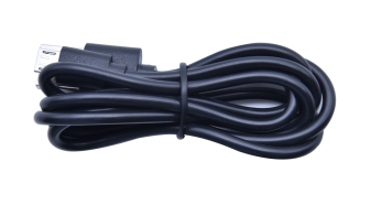
Micro USB Cable*1 |
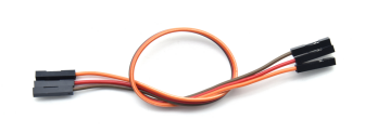
(Note: in all experiments, the micro USB cable is connected to the pico via a Raspberry Pi, and the 3P Dupont wire is torn from a 40P Dupont wire.)
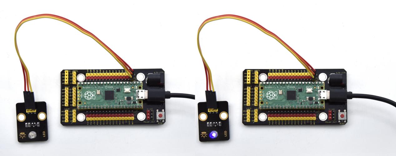
Connection Diagram
Run the test code
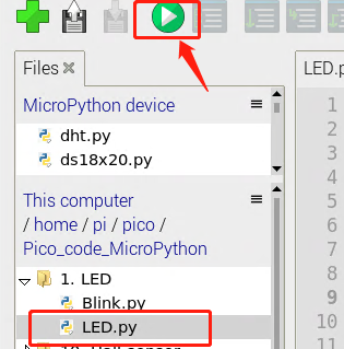
After opening Thonny and connecting to the Pico, click “View” and “Files”, then the code saved on the Raspberry Pi and the Pico will be shown on the left side.
We have saved the code on the Raspberry Pi earlier. Find and click LED.py and Bink.py.
Next, click  to run the code. If it did not work, try clicking
  to stop running, then run the code again. You also can press the reset button on the Pico shield and click to run it again.
Code Explanation
1. Machine
Machine module is indispensable, we will use import machine or from machine import… to program pico with microPython.
2. time.sleep()
This function is used to set delayed time, as time.sleep(0.01), which means, the delayed time is 10ms.
3. led = Pin(0, Pin.OUT)
created a pin example and we name led.
0 is indicative of connected pin GP0, Pin.OUT represents output mode, it can use .value() to output high levels (3.3V) led.value(1) or low levels (0V) led.value(0).
4. import machine
It is used to import modules. When creating pins examples, it will change into led = machine.Pin(0, machine.Pin.OUT).
5. while True
It is loop function.
It means that sentences under this function will loop unless True changes into False. For the function while,led.value(1), outputs high levels to the pin 0; then LED lights up. Then the delayed function time.sleep(1) will wait for 1s. When led.value(0) output low levels to the pin 0, the LED will go off,and the function time.sleep(1) will wait for 1s, cyclically, and LED will flash.
Test Result
Code 1: upload the code and power on, the purple LED on the module will light up
Code 2: upload the code and power on, the purple LED will flash with the interval of 1s.
Test Code
Code 1:
'''
 * Keyestudio 42 in 1 Starter Kit for Raspberry Pi Pico
 * lesson 1.1
 * turn on led
 * turn on led
 * http://www.keyestudio.com
'''
from machine import Pin
led = Pin(0, Pin.OUT)#  create led, connect LED to pin 0,and set pin 0 to OUTPUT
led.value(1)# light up
Code 2:
'''
 * Keyestudio 42 in 1 Starter Kit for Raspberry Pi Pico
 * lesson 1.2
 * Blink
 * http://www.keyestudio.com
'''
from machine import Pin
import time

led = Pin(0, Pin.OUT)# create led, connect LED to pin 0,and set pin0 to OUTPUT
while True:
    led.value(1)# led lights up
    time.sleep(1)# wait for 1s
    led.value(0)# led goes off
    time.sleep(1)# wait for 1s
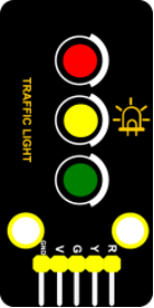
Project 2: Traffic Lights Module

Overview
In this lesson, we will learn how to control multiple LED lights and simulate the operation of traffic lights.
Traffic lights are signal devices positioned at road intersections, pedestrian crossings, and other locations to control flows of traffic.
In this kit, we will use the traffic light module to simulate the traffic light.
Working Principle
In previous lesson, we already know how to control an LED. In this part, we only need to control three separated LEDs. Output high levels to the signal R(3.3V), then the red LED will be on.
Components
|
|
|
|---|---|---|
Raspberry Pi Pico Board*1 |
Raspberry Pi Pico Expansion Board*1 |
Keyestudio DIY Traffic Lights Module*1 |
|
|
|
5P Dupont Wire*1 |
Micro USB Cable*1 |
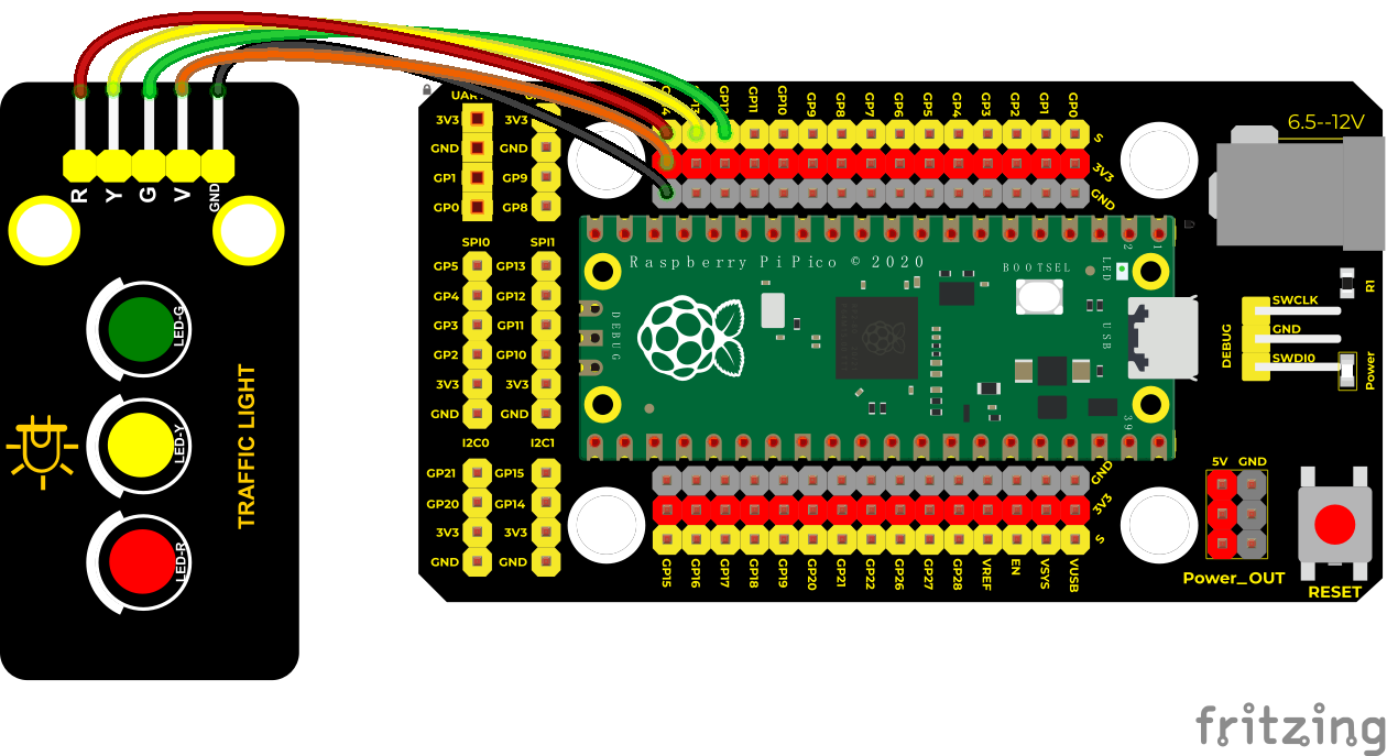
Connection Diagram
Run the test code
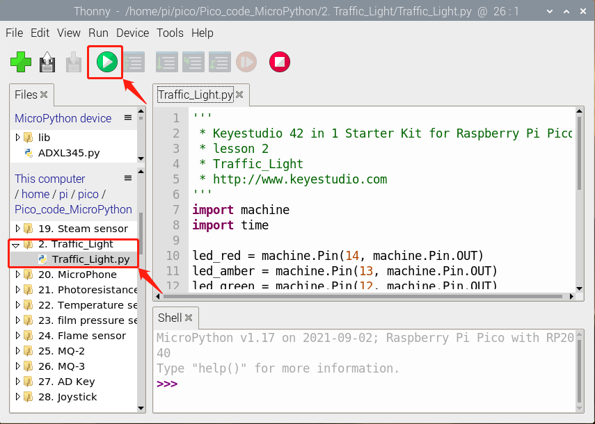
Find and double-click Traffic_Light.py to open it, then click to run the code.
Code Explanation
Create pins, set pins mode and delayed functions.
We use the for loop.
The simplest form is for i in range().
In the code, we used range(3), which means the variable i starts from 0, increase 1 for each time, to 2.
Test Result
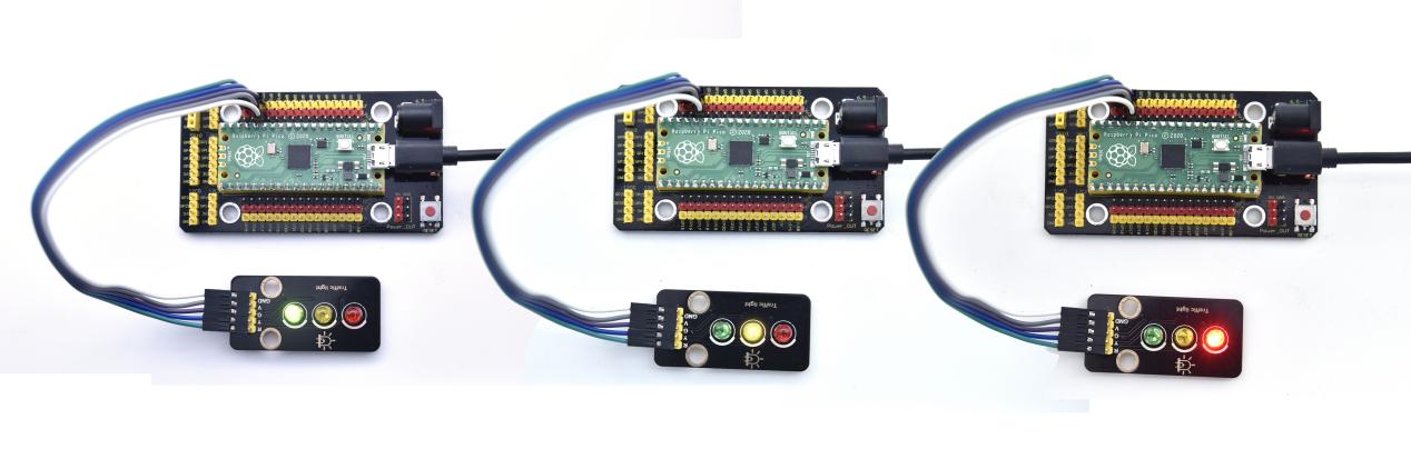
Run the code, the green LED will be on for 5s then off, the yellow LED will flash for 3s then go off and the red one will be on for 5s then off.
Test Code
'''
 * Keyestudio 42 in 1 Starter Kit for Raspberry Pi Pico
 * lesson 2
 * Traffic_Light
 * http://www.keyestudio.com
'''
import machine
import time

led_red = machine.Pin(14, machine.Pin.OUT)
led_amber = machine.Pin(13, machine.Pin.OUT)
led_green = machine.Pin(12, machine.Pin.OUT)

while True:
    led_green.value(1) #  the green LED lights up for 5s
    time.sleep(5)# after 5s
    led_green.value(0)# the green LED will go off
    for i in range(3):#the yellow LED flashes for three times
        led_amber.value(1)
        time.sleep(0.5)
        led_amber.value(0)
        time.sleep(0.5)
    led_red.value(1) # the red LED lights up for 5s
    time.sleep(5)
    led_red.value(0)
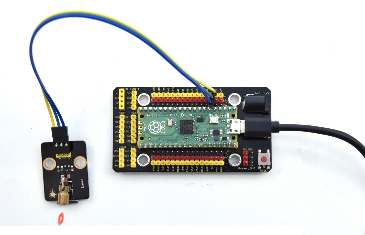
Project 3: Laser Sensor

Description
Lasers are widely used to cut, weld, surface treat, and more on specific materials. The energy of the laser is very high. The toy laser pointer may cause glare to the human eye, and it may cause retinal damage for a long time. my country also prohibits the use of laser to illuminate the aircraft.
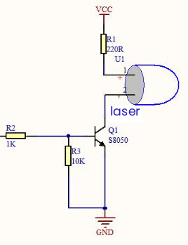
Working Principle
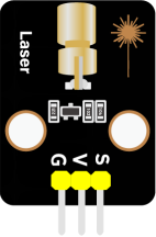
The laser head sensor module is mainly composed of a laser head with a light-emitting die, a condenser lens, and a copper adjustable sleeve.
We can see the circuit schematic diagram of this module which is very similar to the LED we have learned. They are all driven by triodes. A high-level digital signal is directly input at the signal end, then the sensor will start to work; if inputting low levels, the sensor won’t work.
Note: don’t point an laser emitter at eyes of people.
Components
|
|
|
|---|---|---|
Raspberry Pi Pico Board*1 |
Raspberry Pi Pico Expansion Board*1 |
Keyestudio DIY Laser Module*1 |
|
|
|
3P Dupont Wire*1 |
Micro USB Cable*1 |
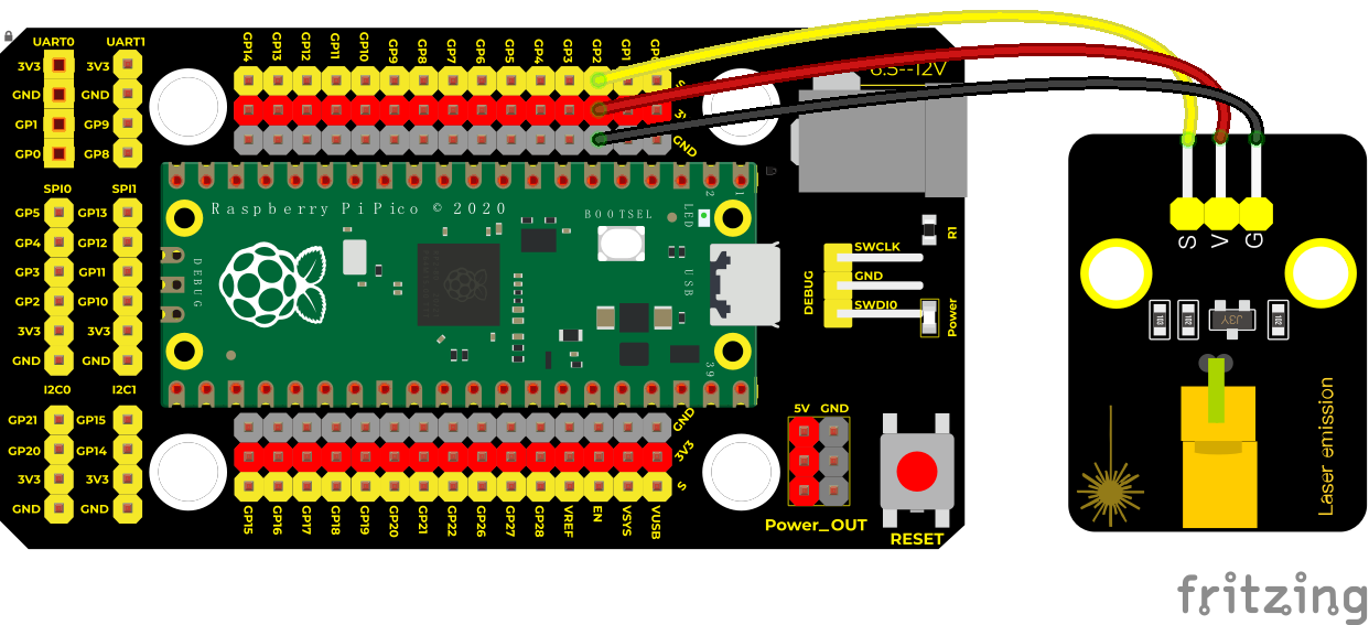
Connection Diagram
Run the test code
Find Laser.py, then double-click the code and click
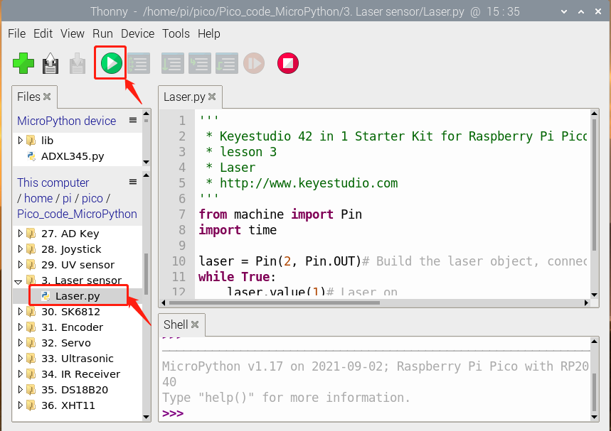
Test Result
Upload the test code and power up, the laser tube on the module emits a red laser signal for 2 seconds, and stops emitting a red laser signal for 2 seconds.
Test Code
'''
 * Keyestudio 42 in 1 Starter Kit for Raspberry Pi Pico
 * lesson 3
 * Laser
 * http://www.keyestudio.com
'''
from machine import Pin
import time

laser = Pin(2, Pin.OUT)# create the laser, connect it to the pin 0 and set the pin 2 to OUTPUT
while True:
    laser.value(1)# the laser module is on
    time.sleep(2)# wait for 2s
    laser.value(0)# the laser module is off
    time.sleep(2)# wait for 2s
Project 4: Button Sensor

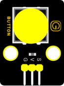
Overview
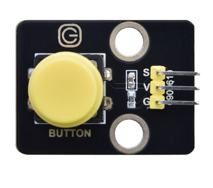
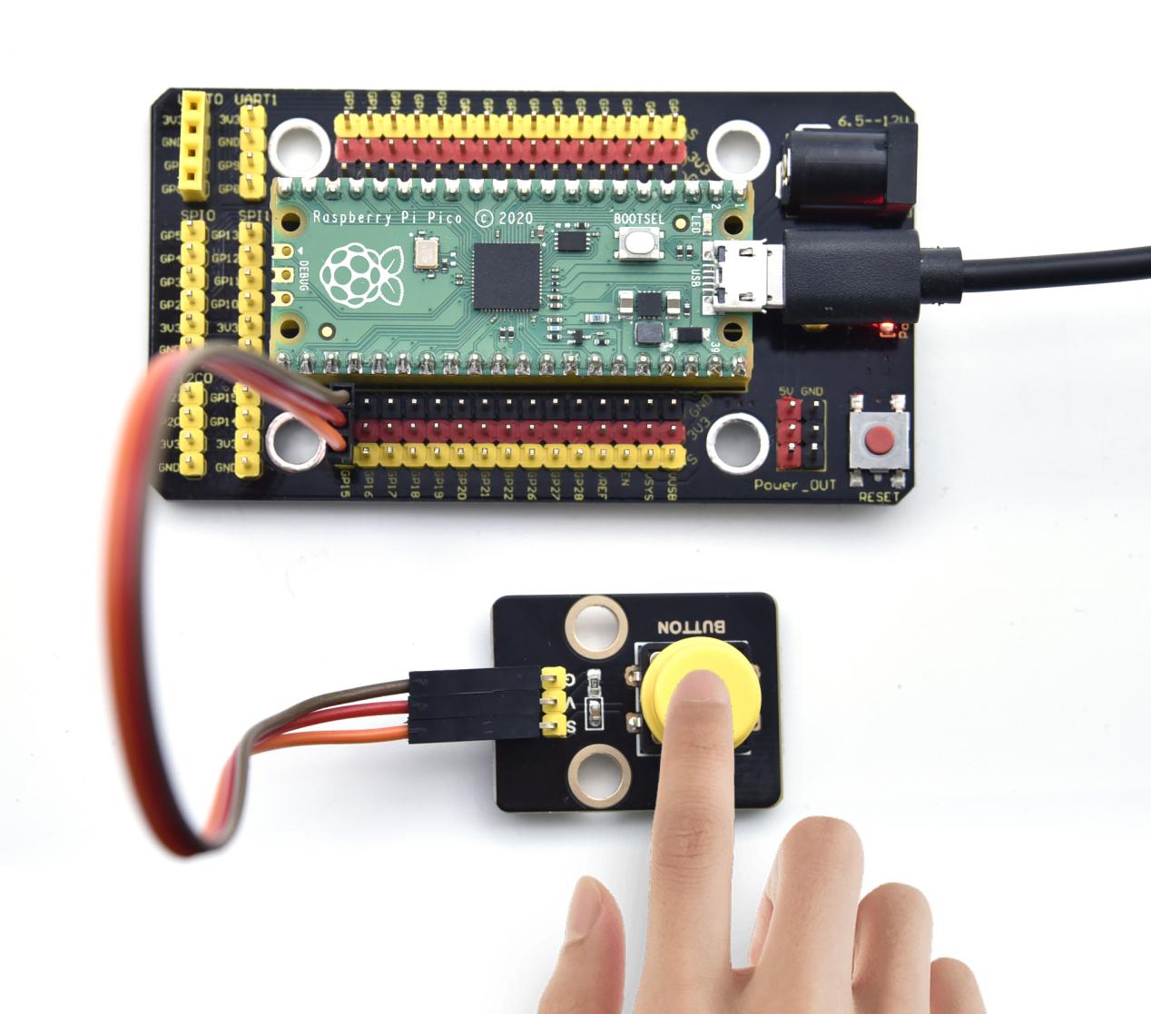
In this kit, there is a Keyestudio single-channel button module, which mainly uses a tact switch and comes with a yellow button cap.
In previous lessons, we learned how to make the pins of our single-chip microcomputer output a high level or low level. In this experiment, we will read the high level (3.3V) and low level (0V).
We can determine whether the button on the sensor is pressed by reading the high and low level of the S terminal on the sensor.
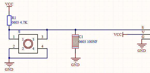
Working Principle
The button module has four pins. The pin 1 is connected to the pin 3 and the pin 2 is linked with the pin 4. When the button is not pressed, they are disconnected. Yet, when the button is pressed, they are connected. If the button is released, the signal end is high level.
Components
|
|
|
|---|---|---|
Raspberry Pi Pico Board*1 |
Raspberry Pi Pico Expansion Board*1 |
Keyestudio DIY Button Module*1 |
|
|
|
3P Dupont Wire*1 |
Micro USB Cable*1 |
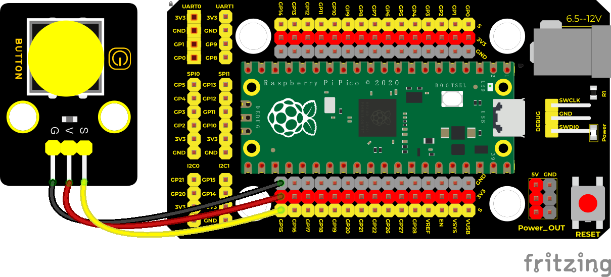
Connection Diagram
Run the test code
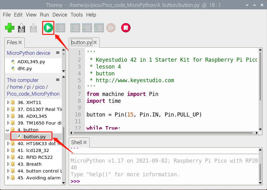
Find button.py,double-click,and click
Code Explanation
1. button = Pin(15, Pin.IN, Pin.PULL_UP),
we define the pin of the button as GP15 and set to PULL-UP mode.
We can use button = Pin(15, Pin.IN) to set INPUT mode, at this time, the pins are in high resistance state.
2. button.value(), read levels of buttons. Function returns High or Low.
3. if..else.. sentence,
4.When the logic judge is TRUE, the code under the if will be activated; otherwise, the code udder the else will be activated.
When pico detects the button pressed, the signal end is low level (GP 15 is low level). button.value() is 0. If pico detects the button unpressed, button.value() is 1 and else sentence will be activated.
Test Result
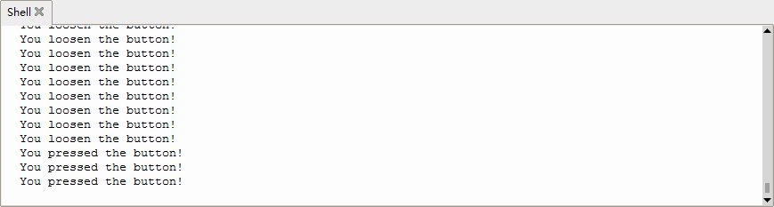
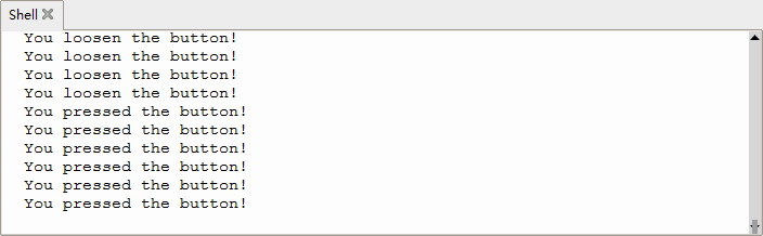
Upload the test code successfully. After powering on the USB cable, open the serial monitor and set the baud rate to 9600. The serial monitor will display the corresponding data and characters. When the button is pressed, val is 0, the monitor will show “Press the button”; when the button is released, val is 1, the monitor will show “Loosen the button”; as shown below.
Test Code
'''
 * Keyestudio 42 in 1 Starter Kit for Raspberry Pi Pico
 * lesson 4
 * button
 * http://www.keyestudio.com
'''
from machine import Pin
import time

button = Pin(15, Pin.IN, Pin.PULL_UP)

while True:
    if button.value() == 0:
        print("You pressed the button!")   #Print information
    else:
        print("You loosen the button!")
    time.sleep(0.1) #delay in 0.1s
Project 5: Capacitive Sensor

Description
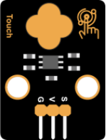
In this kit, there is a capacitive touch module which mainly uses a TTP223-BA6 chip. It is a touch detection chip, which provides a touch button, and its function is to replace the traditional button with a variable area button. When we power on, the sensor needs about 0.5 seconds to stabilize. Do not touch the keys during this time period.
At this time, all functions are disabled, and self-calibration is always performed. The calibration period is about 4 seconds. We display the test results in the shell.
Working Principle
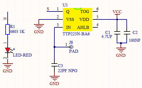
When our fingers touch the module, the signal S outputs high levels, the red LED on the module flashes. We can determine if the button is pressed or not by reading high and low levels on the sensor.
Required Components
|
|
|
|---|---|---|
Raspberry Pi Pico Board*1 |
Raspberry Pi Pico Expansion Board*1 |
Keyestudio DIY Capacitive Module*1 |
|
|
|
3P Dupont Wire*1 |
Micro USB Cable*1 |
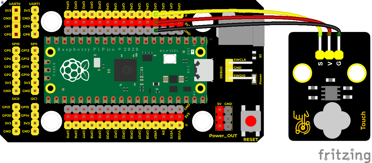
Connection Diagram
Run the test code
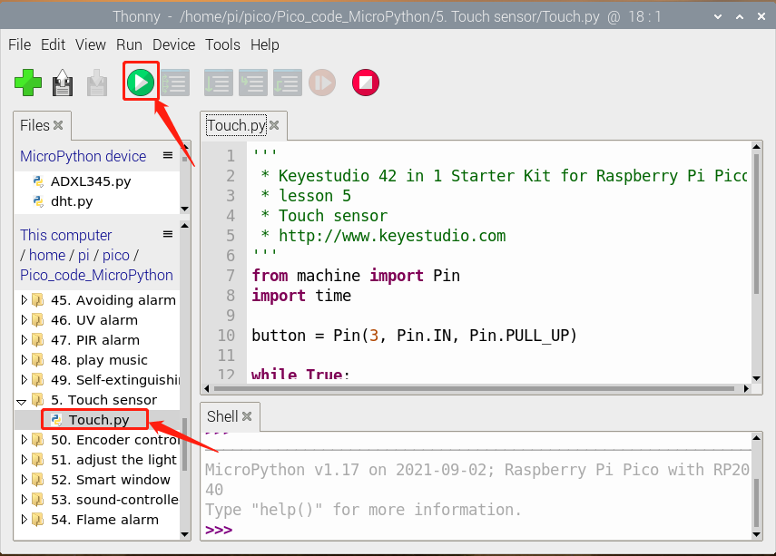
Find Touch.py, double-click and click
Code Explanation
When we touch the sensor, the Shell monitor will show “You pressed the button!”, if not, “You loosen the button!” will be shown on the monitor.
Test Result
The shell monitor shows corresponding data and characters.
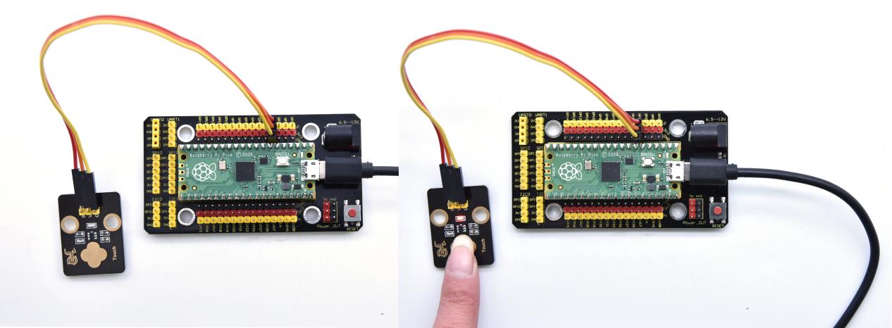
In the experiment, when the button is pressed, the red LED lights up and val is 1. Then the shell shows “You pressed the button!”; if the button is released, the red LED is off and val is 0; “You loosen the button!” will be displayed.
Test Code
'''
 * Keyestudio 42 in 1 Starter Kit for Raspberry Pi Pico
 * lesson 5
 * Touch sensor
 * http://www.keyestudio.com
'''
from machine import Pin
import time

button = Pin(3, Pin.IN, Pin.PULL_UP)

while True:
    if button.value() == 1:
        print("You pressed the button!")   #press to print information
    else:
        print("You loosen the button!")
    time.sleep(0.1) #delay in 0.1s
Project 6: Obstacle Avoidance Sensor

Overview
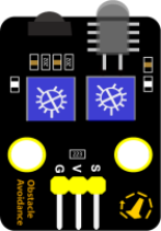
In this kit, there is a Keyestudio obstacle avoidance sensor, which mainly uses an infrared emitting and a receiving tube. In the experiment, we will determine whether there is an obstacle by reading the high and low level of the S terminal on the sensor.
Working Principle
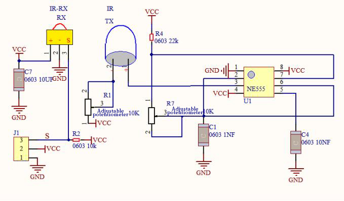
NE555 circuit provides IR signals with frequency to the emitter TX, then the IR signals will fade with the increase of transmission distance. If encountering the obstacle, it will be reflected back.
When the receiver RX meets the weak signals reflected back, the receiving pin will output high levels, which indicates the obstacle is far away. On the contrary, it the reflected signals are stronger, low levels will be output, which represents the obstacle is close. There are two potentiometers on the module, and one is for adjusting emission power, another one is for receiving frequency.
Components
|
|
|
|---|---|---|
Raspberry Pi Pico Board*1 |
Raspberry Pi Pico Expansion Board*1 |
Keyestudio DIY Obstacle Avoidance Sensor*1 |
|
|
|
3P Dupont Wire*1 |
Micro USB Cable*1 |
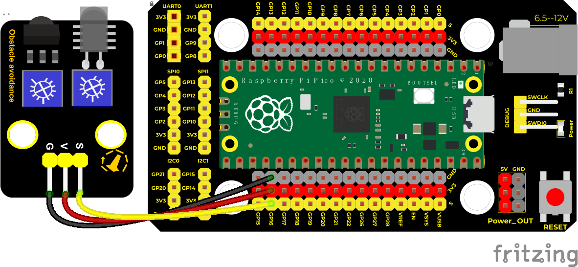
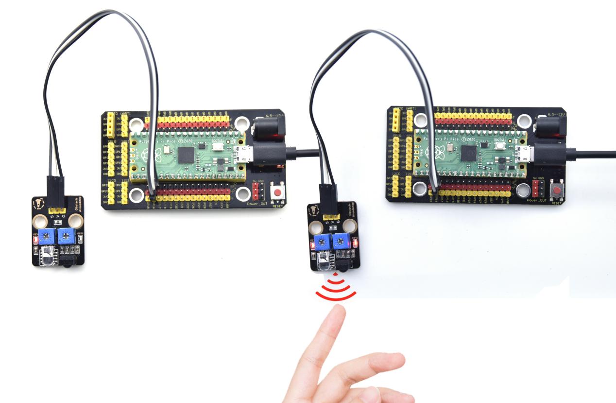
Connection Diagram
Run the test code
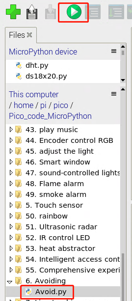
Find Avoid.py, double-click and click.
Code Explanation
Run the code, we start to adjust the two potentiometers to sense distance.
Adjust the potentiometer transmitting power. Make the P LED at the critical point of ON and OFF states.
Adjust the potentiometer receiving frequency. Rotate it clockwise, the frequency will increase. Make the S LED at the critical point of ON and OFF states, then the 38KHz square wave can be produced.
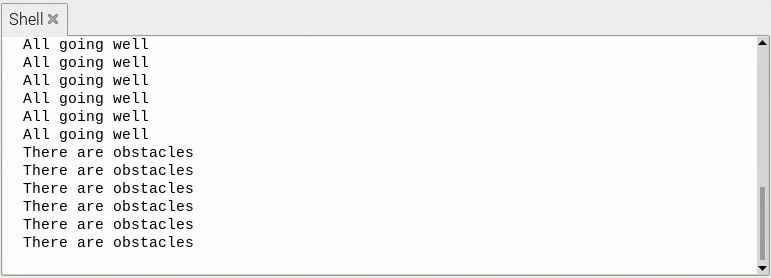
Test Result
Run the code, when the sensor detects the obstacle, the Shell will show “There are obstacles”; if the obstacle is not detected, “All going well” will be shown.
Test Code
'''
 * Keyestudio 42 in 1 Starter Kit for Raspberry Pi Pico
 * lesson 6
 * Infrared obstacle avoidance sensor
 * http://www.keyestudio.com
'''
from machine import Pin
import time

sensor = Pin(16, Pin.IN)
while True:
    if sensor.value() == 0:
        print("There are obstacles")
    else:
        print("All going well")
time.sleep(0.1)
Project 7: Line Tracking Sensor
Description
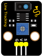
In this kit, there is a DIY electronic building block single-channel line tracking sensor which mainly uses a TCRT5000 reflective black and white line recognition sensor element.
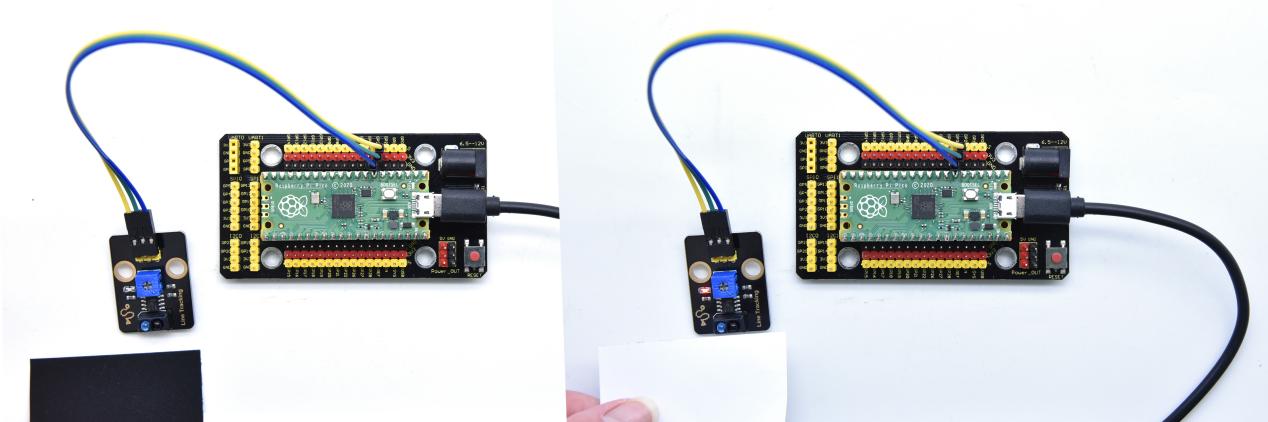
In the experiment, we judge the color (black and white) of the object detected by the sensor by reading the high and low levels of the S terminal on the module; and display the test results on the shell.
Working Principle
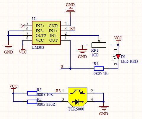
When a black or no object is detected, the signal terminal will output high levels; when white object is detected, the signal terminal is low level; its detection height is 0-3cm. We can adjust the sensitivity by rotating the potentiometer on the sensor. When the potentiometer is rotated, the sensitivity is best when the red LED on the sensor is at the critical point between off and on.
Required Components
|
|
|
|---|---|---|
Raspberry Pi Pico Board*1 |
Raspberry Pi Pico Expansion Board*1 |
Keyestudio DIY Line Tracking Sensor*1 |
|
|
|
3P Dupont Wire*1 |
Micro USB Cable*1 |
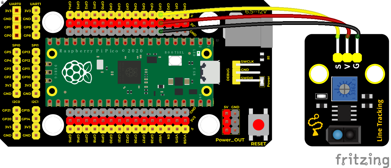
Connection Diagram
Run the test code
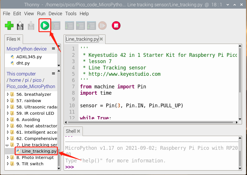
Find Line_tracking.py,double-click and click
Test Result
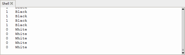
Upload test code, the shell displays the corresponding data and characters. In the experiment, when the sensor doesn’t detect an object or detects a black object, the val is 1, and the shell will display “Black” ; when a white object (can reflect light) is detected, the val is 0, and the shell displays “White” ;
Test Code
'''
 * Keyestudio 42 in 1 Starter Kit for Raspberry Pi Pico
 * lesson 7
 * Line Tracking sensor
 * http://www.keyestudio.com
'''
from machine import Pin
import time

sensor = Pin(3, Pin.IN, Pin.PULL_UP)

while True:
    if sensor.value() == 0:
        print("0   White")   #print information
    else:
        print("1   Black")
    time.sleep(0.1) #delay in 0.1s
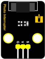
Project 8: Photo Interrupter
Description
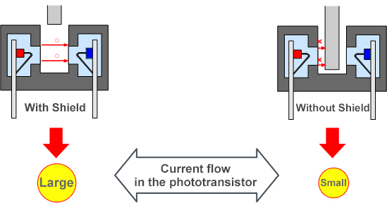
This kit contains a photo interrupter which mainly uses 1 ITR-9608 photoelectric switch. It is a photoelectric switch optical switch sensor.
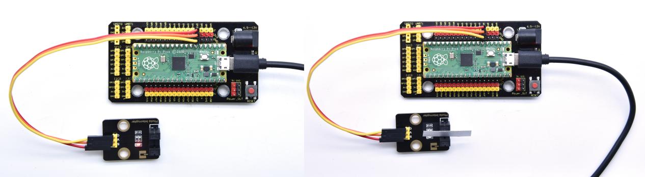
Working Principle
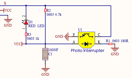
When the paper is put in the slot, C is connected with VCC and the signal end S of the sensor are high levels; then the red LED will be off. Otherwise, the red LED will be on.
Required Components
|
|
|
|---|---|---|
Raspberry Pi Pico Board*1 |
Raspberry Pi Pico Expansion Board*1 |
Keyestudio DIY Photo Interrupter*1 |
|
|
|
3P Dupont Wire*1 |
Micro USB Cable*1 |
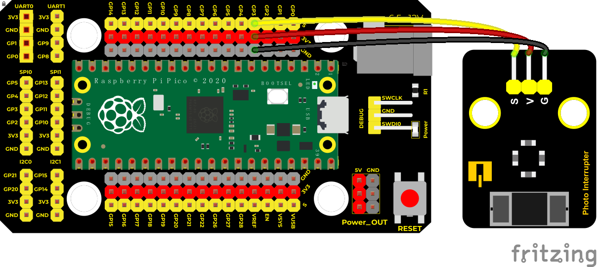
Connection Diagram
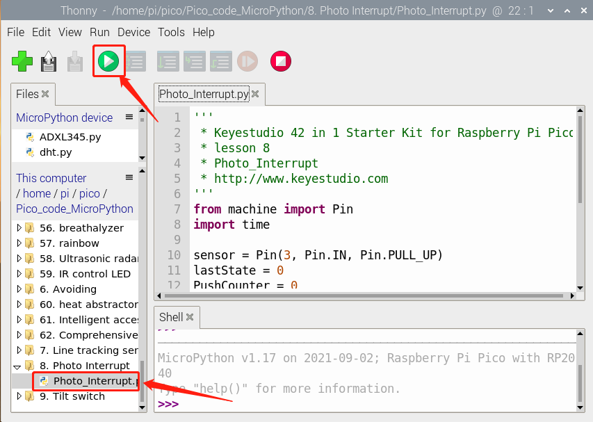
Run the test code
Find Photo_Interrupt.py,double-click and click
Code Explanation
Logic setting:
Initial Setting |
Set PushCounter to 0 |
|
|---|---|---|
when an object enters the slot |
lastState is 0,State turns into 1; |
Set PushCounter to PushCounter+1 |
when the object leaves the slot |
lastState is 1,State becomes 0, |
PushCounter doesn’t change; |
When the object goes |
lastState is 0, State becomes 1, |
Set PushCounter to PushCounter+1 |
When the object |
lastState is 1,State turns into 0, |
PushCounter doesn’t change; |
Test Result
Wire up, upload test code, and the shell displays the PushCounter data. Every time when the object passes through the slot of the sensor, the PushCounter data will increase by 1 continuously, as shown below;
Test Code
'''
 * Keyestudio 42 in 1 Starter Kit for Raspberry Pi Pico
 * lesson 8
 * Photo_Interrupt
 * http://www.keyestudio.com
'''
from machine import Pin
import time

sensor = Pin(3, Pin.IN, Pin.PULL_UP)
lastState = 0
PushCounter = 0

while True:
    State = sensor.value()
    if  State != lastState:
        if State == 1:
            PushCounter += 1
            print(PushCounter)   #press to print information
    lastState = State
Project 9: Tilt Module

Overview
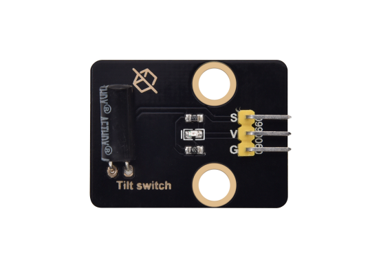
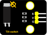
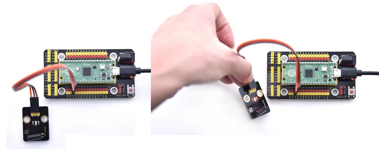
In this kit, there is a Keyestudio tilt sensor. The tilt switch can output signals of different levels according to whether the module is tilted. There is a ball inside. When the switch is higher than the horizontal level, the switch is turned on, and when it is lower than the horizontal level, the switch is turned off. This tilt module can be used for tilt detection, alarm or other detection.
Working Principle
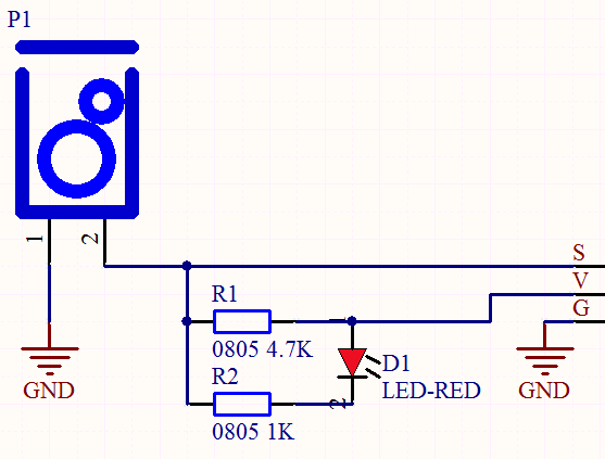
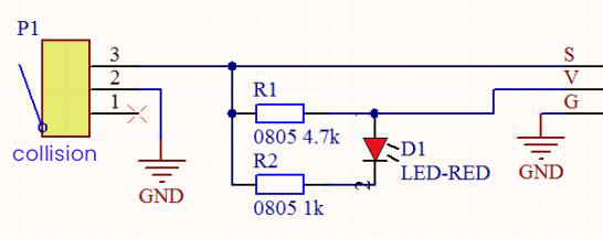
The working principle is pretty simple. When pin 1 and 2 of the ball switch P1 are connected, the signal S is low level and the red LED will light up; when they are disconnected, the pin will be pulled up by the 4.7K R1 and make S a high level, then LED will be off.
Components
|
|
|
|---|---|---|
Raspberry Pi Pico Board*1 |
Raspberry Pi Pico Expansion Board*1 |
Keyestudio Tilt Sensor*1 |
|
|
|
3P Dupont Wire*1 |
Micro USB Cable*1 |
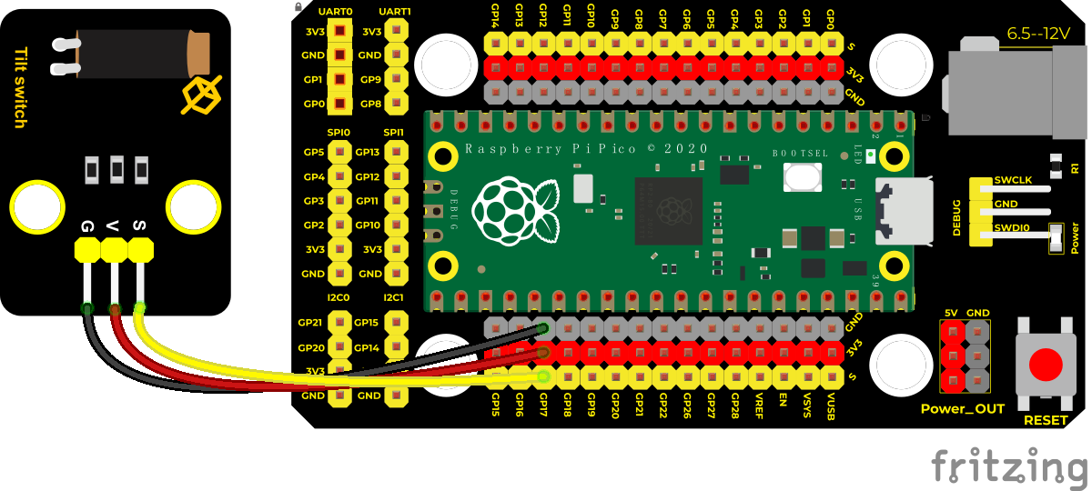
Connection Diagram
Run the test code
Find Tilt switch.py, double-click and click.
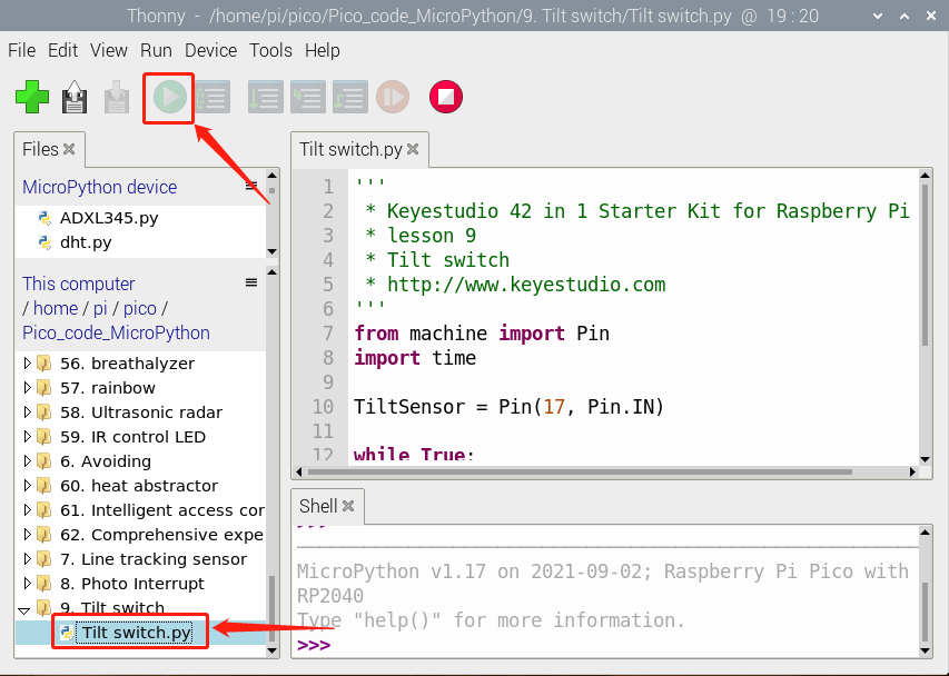
Test Result
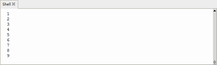
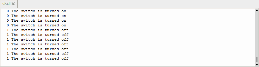
Upload the test code and observe Shell.
When the tilt module is inclined to one side, the red LED on the module will be off and the monitor will display“1 The switch is turned off”. In contrast, if you make it incline the other side, the red LED will light up and the monitor will display“0 The switch is turned on”.
Test Code
'''
 * Keyestudio 42 in 1 Starter Kit for Raspberry Pi Pico
 * lesson 9
 * Tilt switch
 * http://www.keyestudio.com
'''
from machine import Pin
import time

TiltSensor = Pin(17, Pin.IN)

while True:
    value = TiltSensor.value()
    print(value, end = " ")
    if  value== 0:
        print("The switch is turned on")
    else:
        print("The switch is turned off")
    time.sleep(0.1)
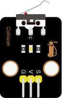
Project 10: Collision Sensor

Description
The collision sensor uses a tact switch. This sensor is often used as a limit switch in 3D printers. In the experiment, we judge whether the sensor shrapnel is pressed down by reading the high and low levels of the S terminal on the module; and, we display the test results in the shell.
Working Principle
It mainly uses a tact switch. When the shrapnel of the tact switch is pressed, 2 and 3 are connected, the signal terminal S is low level, and the red LED on the module lights up; when the touch switch is not pressed, 2 and 3 are not connected, and 3 is pulled up to a high level by the 4.7K resistor R1, that is, the sensor signal terminal S is a high level, and the built-in red LED will be off at this time.
Components Required
|
|
|
|---|---|---|
Raspberry Pi Pico Board*1 |
Raspberry Pi Pico Expansion Board*1 |
Keyestudio Collision Sensor*1 |
|
|
|
3P Dupont Wire*1 |
Micro USB Cable*1 |
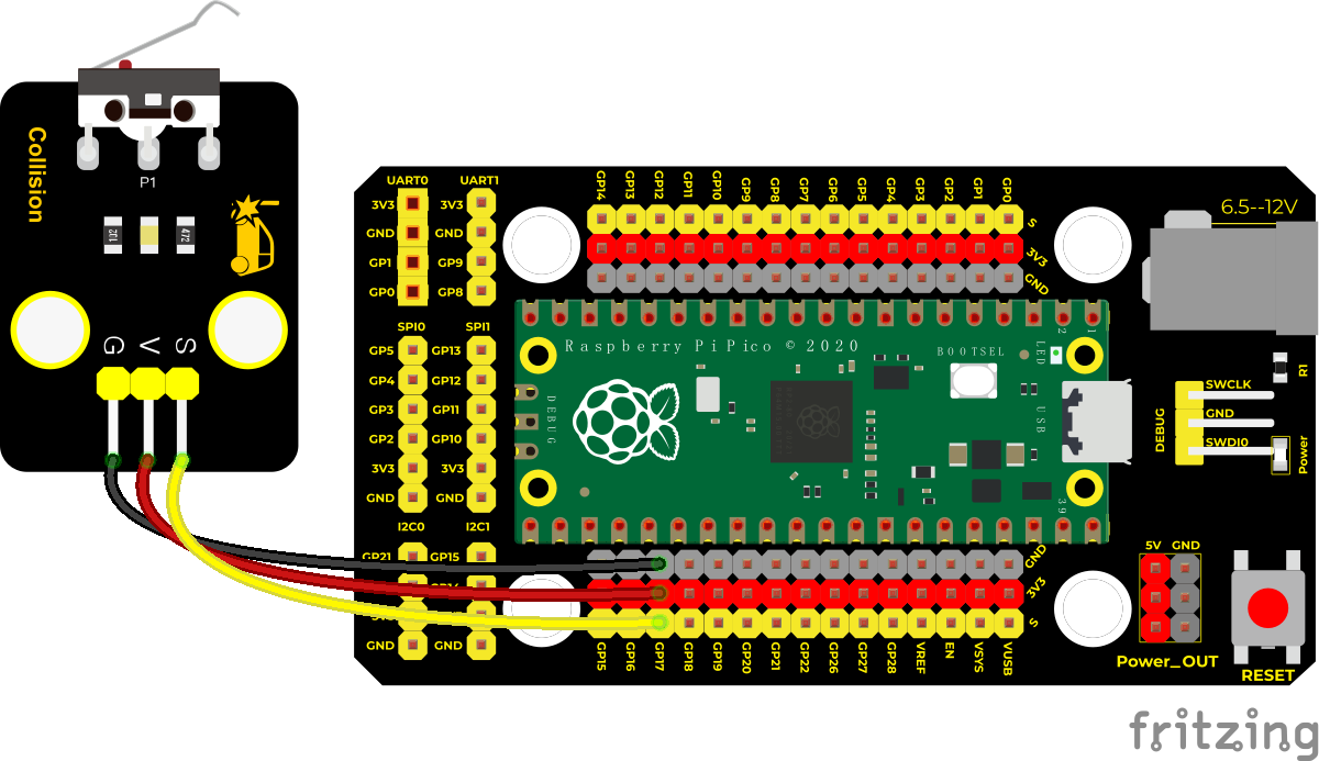
Connection Diagram
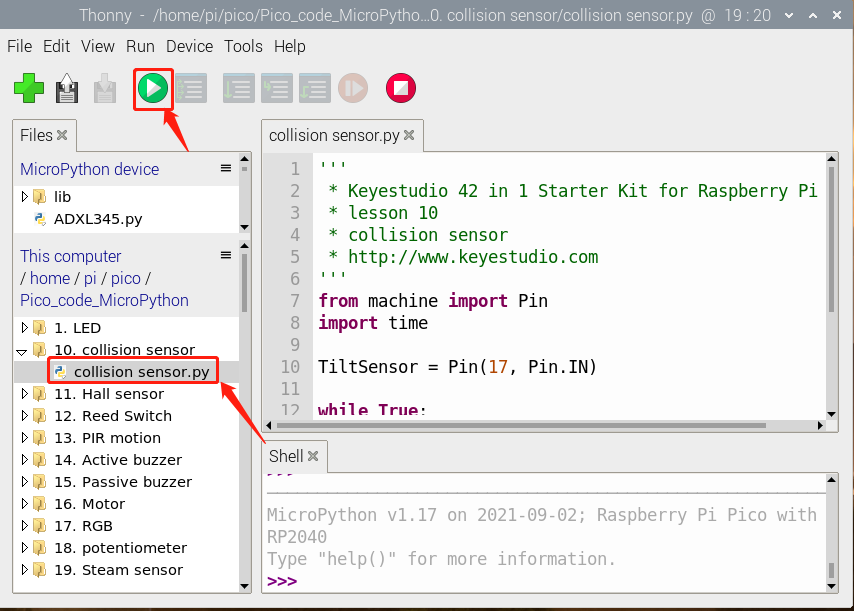
Run the test code
Find collision sensor.py,double-click and click
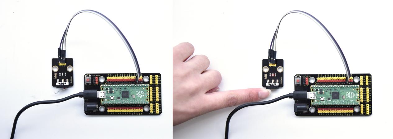
Test Result
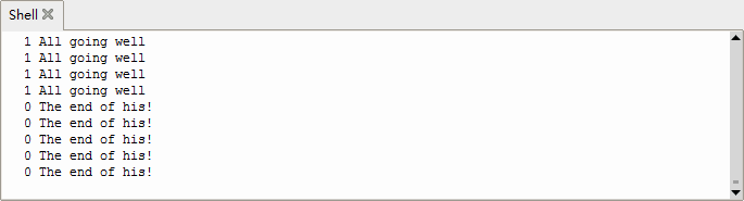
Run the test code, the shell displays the corresponding data and characters. In the experiment, when the shrapnel on the sensor is pressed down, val is 0, the red LED of the module is on, and “The end of his!” is printed; when the shrapnel is released, the val is 1, the red LED of the module is off, and “All going well” is printed. !” character, as shown below.
Test Code
'''
 * Keyestudio 42 in 1 Starter Kit for Raspberry Pi Pico
 * lesson 10
 * collision sensor
 * http://www.keyestudio.com
'''
from machine import Pin
import time

TiltSensor = Pin(17, Pin.IN)

while True:
    value = TiltSensor.value()
    print(value, end = " ")
    if  value== 0:
        print("The end of his!")
    else:
        print("All going well")
    time.sleep(0.1)
Project 11: Hall Sensor

Description
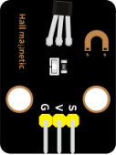
In this kit, there is a Hall sensor which mainly adopts a A3144 linear Hall element. The element P1 is composed of a voltage regulator, a Hall voltage generator, a differential amplifier, a Schmitt trigger, a temperature compensation circuit and an open-collector output stage. In the experiment, we use the Hall sensor to detect the magnetic field and display the test results on the shell.
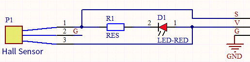
Working Principle
When the sensor detects no magnetic field or a north pole magnetic field, the signal terminal will be high level; when it senses a south pole magnetic field, the signal terminal will be low levels.
The stronger the magnetic field strength is, induction distance is longer.
Required Components
|
|
|
|---|---|---|
Raspberry Pi Pico Board*1 |
Raspberry Pi Pico Expansion Board*1 |
Keyestudio DIY Hall Sensor*1 |
|
|
|
3P Dupont Wire*1 |
Micro USB Cable*1 |
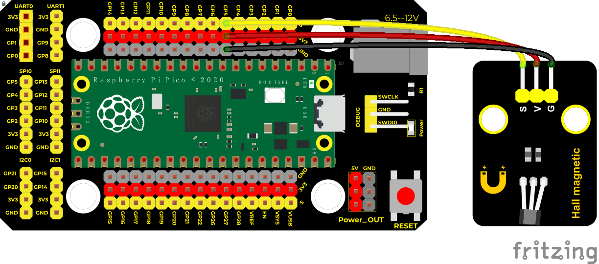
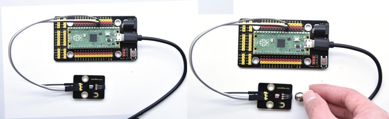
Connection Diagram
Run the test code
Find and double-click Hall.py and click
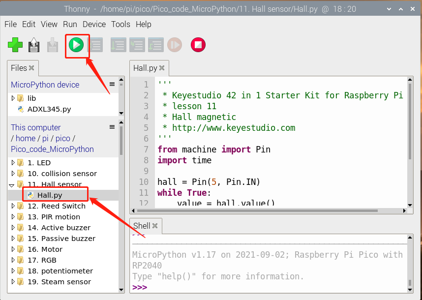
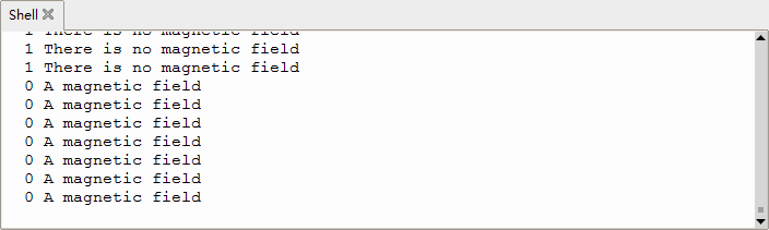
Test Result
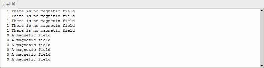
Upload the test code, when the sensor detects no magnetic fields or the north pole magnetic field, Shell will show “1 There is no magnetic field” and the LED on the sensor will be off; When it detects the south pole magnetic field, the Shell will show “0 A magnetic field” and the LED on the sensor will be off.
Test Code
'''
 * Keyestudio 42 in 1 Starter Kit for Raspberry Pi Pico
 * lesson 11
 * Hall magnetic
 * http://www.keyestudio.com
'''
from machine import Pin
import time

hall = Pin(5, Pin.IN)
while True:
    value = hall.value()
    print(value, end = " ")
    if value == 0:
        print("A magnetic field")
    else:
        print("There is no magnetic field")
    time.sleep(0.1)
Project 12: Reed Switch Module

Overview
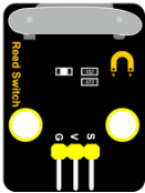
In this kit, there is a Keyestudio reed switch module, which mainly uses a MKA10110 green reed component.
The reed switch is the abbreviation of the dry reed switch. It is a passive electronic switch element with contacts.
It has the advantages of simple structure, small size and easy control.
Its shell is a sealed glass tube with two iron elastic reed electric plates.
In the experiment, we will determine whether there is a magnetic field near the module by reading the high and low level of the S terminal on the module; and, we display the test result in the shell.
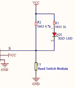
Working Principle
Reed switch is an abbreviation of the dry reed contacts a passive electronic switching elements, and has the advantages of simple structure, small size and ease of control, its shell is a sealed glass tube, the tubes are installed two iron elastic reed plate, but also filling called rhodium metal inert gas. In peacetime, the glass tube in the two reeds made of special materials are separated.
When a magnetic substance close to the glass tube, in the role of the magnetic field lines, the pipe within the two reeds are magnetized to attract each other in contact, the reed will suck together, so that the junction point of the connected circuit communication. After the disappearance of the outer magnetic reed because of their flexibility and separate, the line is disconnected. Therefore, as a use of the magnetic field signals to control the line switching device, reed tube can be used as a sensor for counting the number, spacing, etc., and also are widely used in a variety of communication devices.
Components
|
|
|
|---|---|---|
Raspberry Pi Pico Board*1 |
Raspberry Pi Pico Expansion Board*1 |
Keyestudio DIY Reed Switch Module*1 |
|
|
|
3P Dupont Wire*1 |
Micro USB Cable*1 |
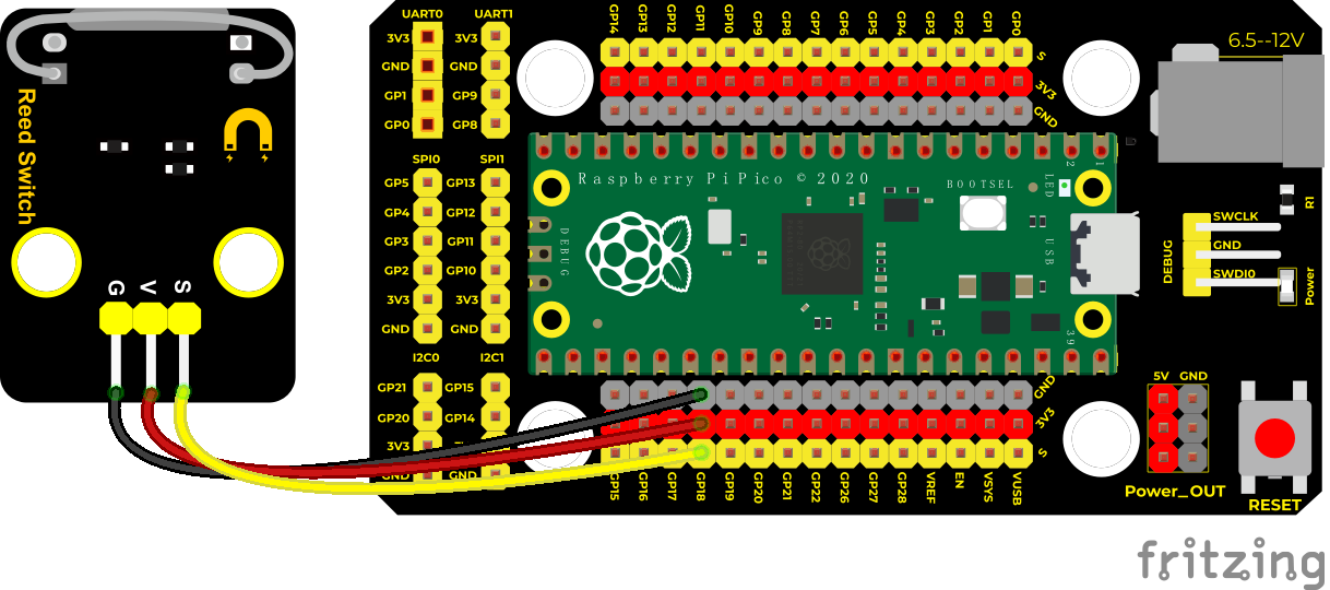
Connection Diagram
Run the test code
Find Reed Switch.py, double-click and click
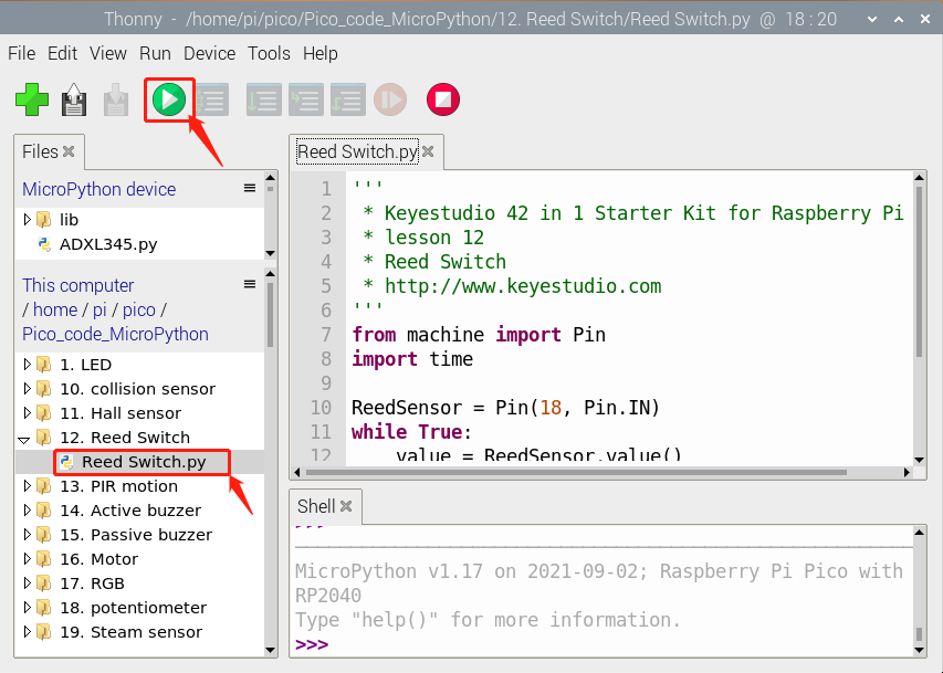
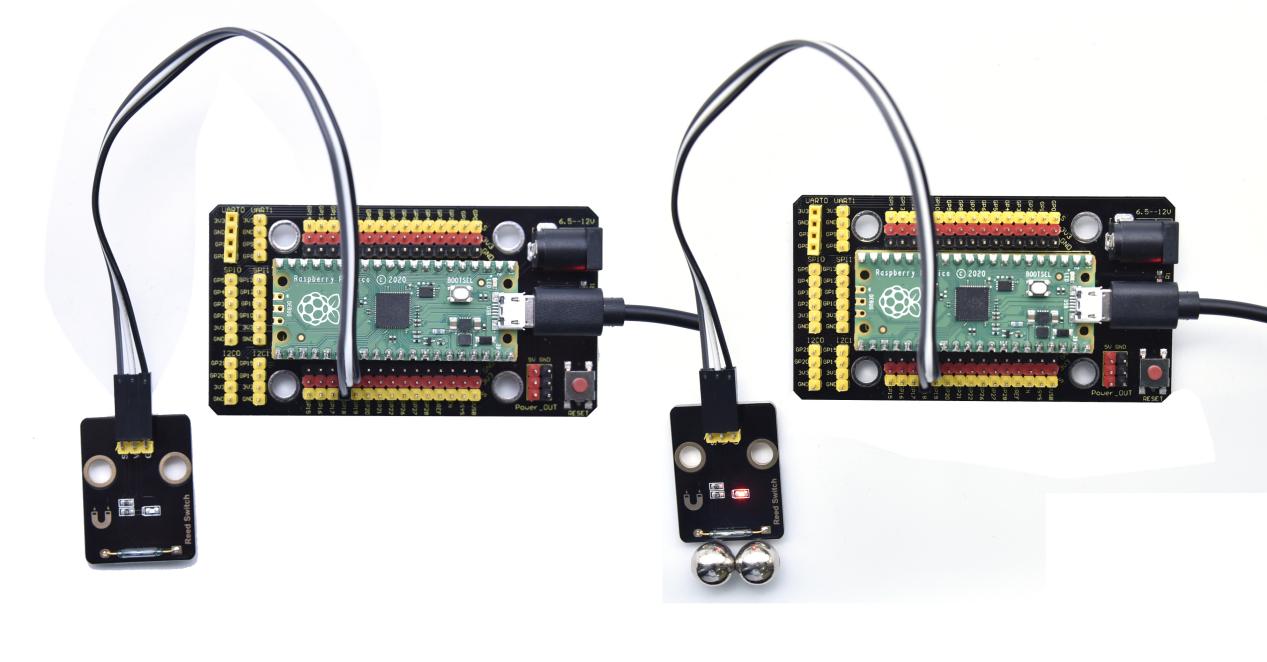
Test Result
Upload the code and observe the Shell monitor. When the sensor detects a magnetic field, val is 0 and the red LED of the module lights up, “A magnetic field” will be displayed; when no magnetic field is detected, val is 1, and the LED on the module goes out, “There is no magnetic field” will be shown, as shown below.
Test Code
'''
 * Keyestudio 42 in 1 Starter Kit for Raspberry Pi Pico
 * lesson 12
 * Reed Switch
 * http://www.keyestudio.com
'''
from machine import Pin
import time

ReedSensor = Pin(18, Pin.IN)
while True:
    value = ReedSensor.value()
    print(value, end = " ")
    if value == 0:
        print("A magnetic field")
    else:
        print("There is no magnetic field")
    time.sleep(0.1)
Project 13: PIR Motion Sensor
Overview
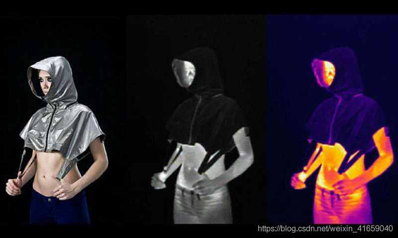
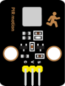
In this kit, there is a Keyestudio PIR motion sensor, which mainly uses an RE200B-P sensor elements. It is a human body pyroelectric motion sensor based on pyroelectric effect, which can detect infrared rays emitted by humans or animals, and the Fresnel lens can make the sensor’s detection range farther and wider.
In the experiment, we determine if there is someone moving nearby by reading the high and low levels of the S terminal on the module. The detected results will be displayed on the Shell.
Working Principle
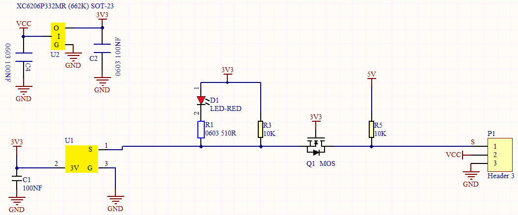
The upper left part is voltage conversion(VCC to 3.3V). The working voltage of sensors we use is 3.3V, therefore we can’t use 5V directly. The voltage conversion circuit is needed.
When no person is detected or no infrared signal is received, and pin 1 of the sensor outputs low level. At this time, the LED on the module will light up and the MOS tube Q1 will be connected and the signal terminal S will detect Low levels.
When one is detected or an infrared signal is received, and pin 1 of the sensor outputs a high level. Then LED on the module will go off, the MOS tube Q1 is disconnected and the signal terminal S will detect high levels.
Required Components
|
|
|
|---|---|---|
Raspberry Pi Pico Board*1 |
Raspberry Pi Pico Expansion Board*1 |
Keyestudio DIY PIR Motion Sensor*1 |
|
|
|
3P Dupont Wire*1 |
Micro USB Cable*1 |
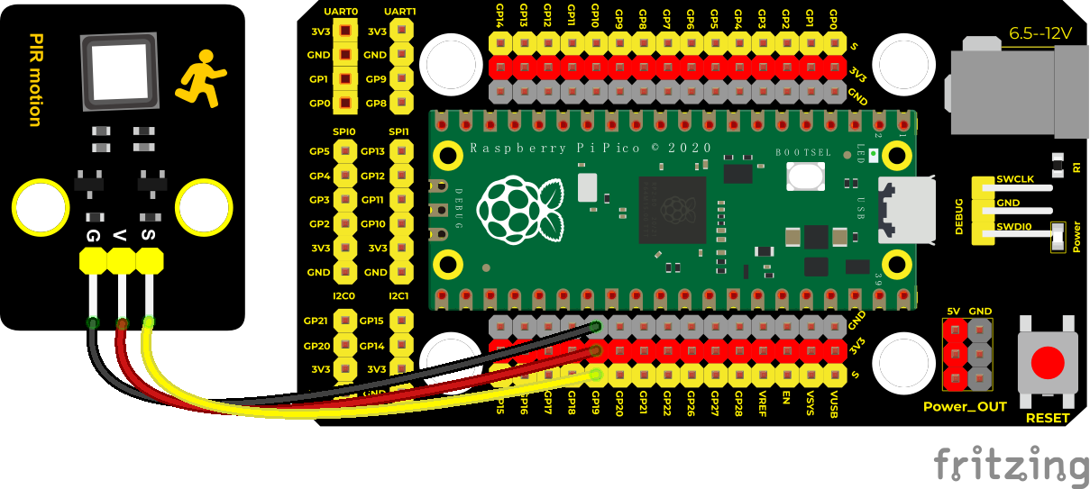
Connection Diagram
Run the Test Code
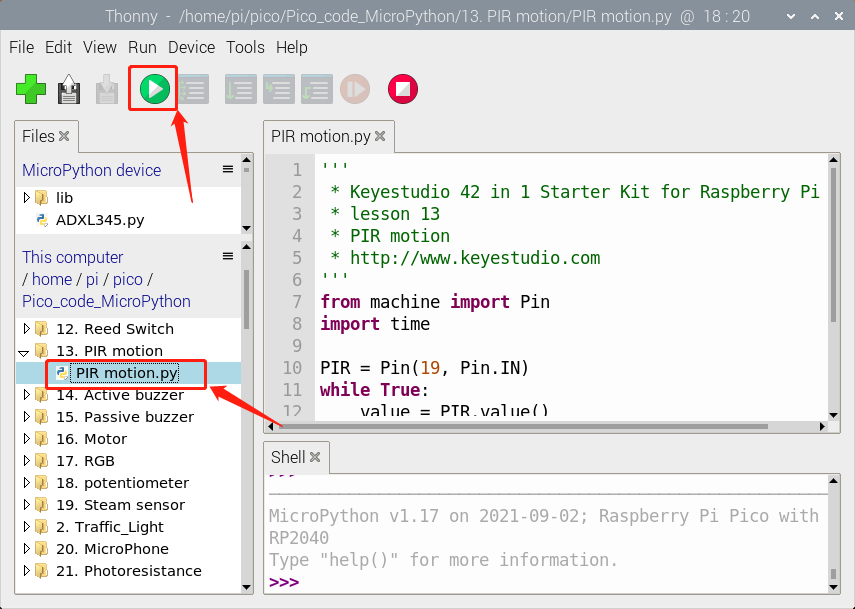
Find and double-click PIR motion.py to open it, click to run the code.
Test Result
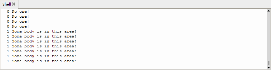
Upload the code and open the Shell monitor.
When the sensor detects someone nearby, value is 1, the LED will go off and the monitor will show “Somebody is in this area!”. On the contrary, the value is 0, the LED will go up and “0 No one!” will be shown.
Test Code
'''
 * Keyestudio 42 in 1 Starter Kit for Raspberry Pi Pico
 * lesson 13
 * PIR motion
 * http://www.keyestudio.com
'''
from machine import Pin
import time

PIR = Pin(19, Pin.IN)
while True:
    value = PIR.value()
    print(value, end = " ")
    if value == 1:
        print("Some body is in this area!")
    else:
        print("No one!")
    time.sleep(0.1)
Project 14: Active Buzzer

Overview
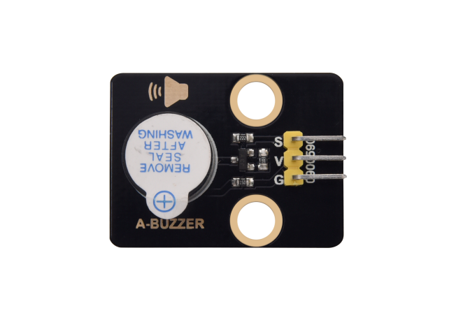
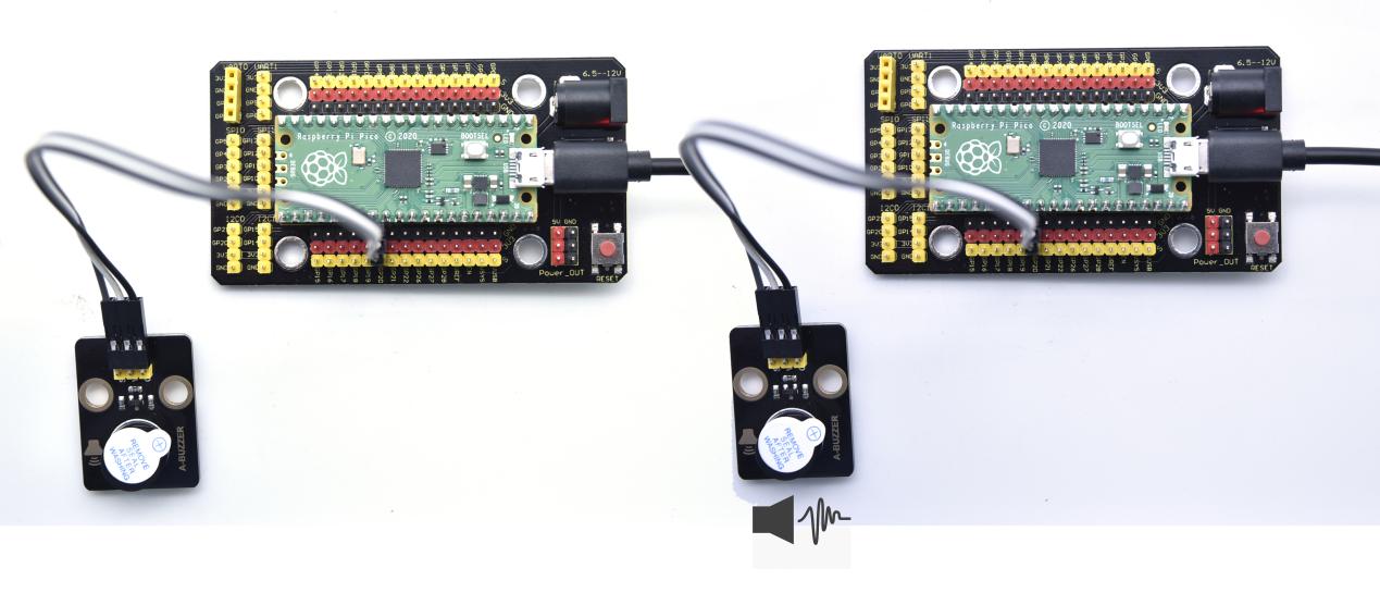
In this kit, it contains an active buzzer module and a power amplifier module (the principle is equivalent to a passive buzzer). In this experiment, we control the active buzzer to emit sounds. Since it has its own oscillating circuit, the buzzer will automatically sound if given large voltage.
Working Principle
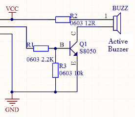
From the schematic diagram, the pin of buzzer is connected to a resistor R2 and another port is linked with a NPN triode Q1. So, if this triode Q1 is powered, the buzzer will sound.
If the base electrode of the triode connected to the R1 resistor is a high level, the triode Q1 will be connected.If the base electrode is pulled down by the resistor R3, the triode is disconnected.
When we output a high level from the IO port to the triode, the buzzer will emit sounds; if outputting low levels, the buzzer won’t emit sounds.
Components
|
|
|
|---|---|---|
Raspberry Pi Pico Board*1 |
Raspberry Pi Pico Expansion Board*1 |
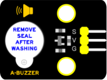
Keyestudio Active Buzzer*1 |
|
|
|
3P Dupont Wire*1 |
Micro USB Cable*1 |
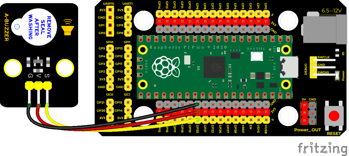
Connection Diagram
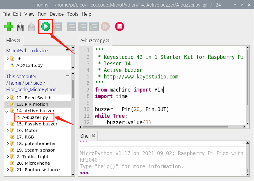
Run the Test Code
Find and double-click A-buzzer.py to open it, then click to run the code.
Code Explanation
In the experiment, we set the pin number to 20. When setting to high, the active buzzer will beep; when setting to low, the active buzzer will stop emitting sounds
Test Result
Upload the code and power on. The active buzzer will emit sound for 1 second, and stop for 1 second.
Test Code
'''
 * * Keyestudio 42 in 1 Starter Kit for Raspberry Pi Pico
 * lesson 14
 * Active buzzer
 * http://www.keyestudio.com
'''
from machine import Pin
import time

buzzer = Pin(20, Pin.OUT)
while True:
    buzzer.value(1)
    time.sleep(1)
    buzzer.value(0)
    time.sleep(1)
Project 15: 8002b Audio Power Amplifier

Overview
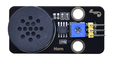
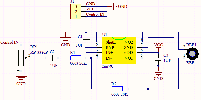
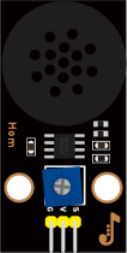
In this kit, there is a Keyestudio 8002b audio power amplifier. The main components of this module are an adjustable potentiometer, a speaker, and an audio amplifier chip;
The main function of this module is: it can amplify the output audio signal, with a magnification of 8.5 times, and play sound or music through the built-in low-power speaker, as an external amplifying device for some music playing equipment.
In the experiment, we used the 8002b power amplifier speaker module to emit sounds of various frequencies.
Working Principle
In fact, it is similar to a passive buzzer. The active buzzer has its own oscillation source. Yet, the passive buzzer does not have internal oscillation. When controlling the circuit, we need to input square waves of different frequencies to the positive pole of the component and ground the negative pole to control the buzzer to chime sounds of different frequencies.
Components
|
|
|
|---|---|---|
Raspberry Pi Pico Board*1 |
Raspberry Pi Pico Expansion Board*1 |
Keyestudio 8002b Audio Power Amplifier*1 |
|
|
|
3P Dupont Wire*1 |
Micro USB Cable*1 |
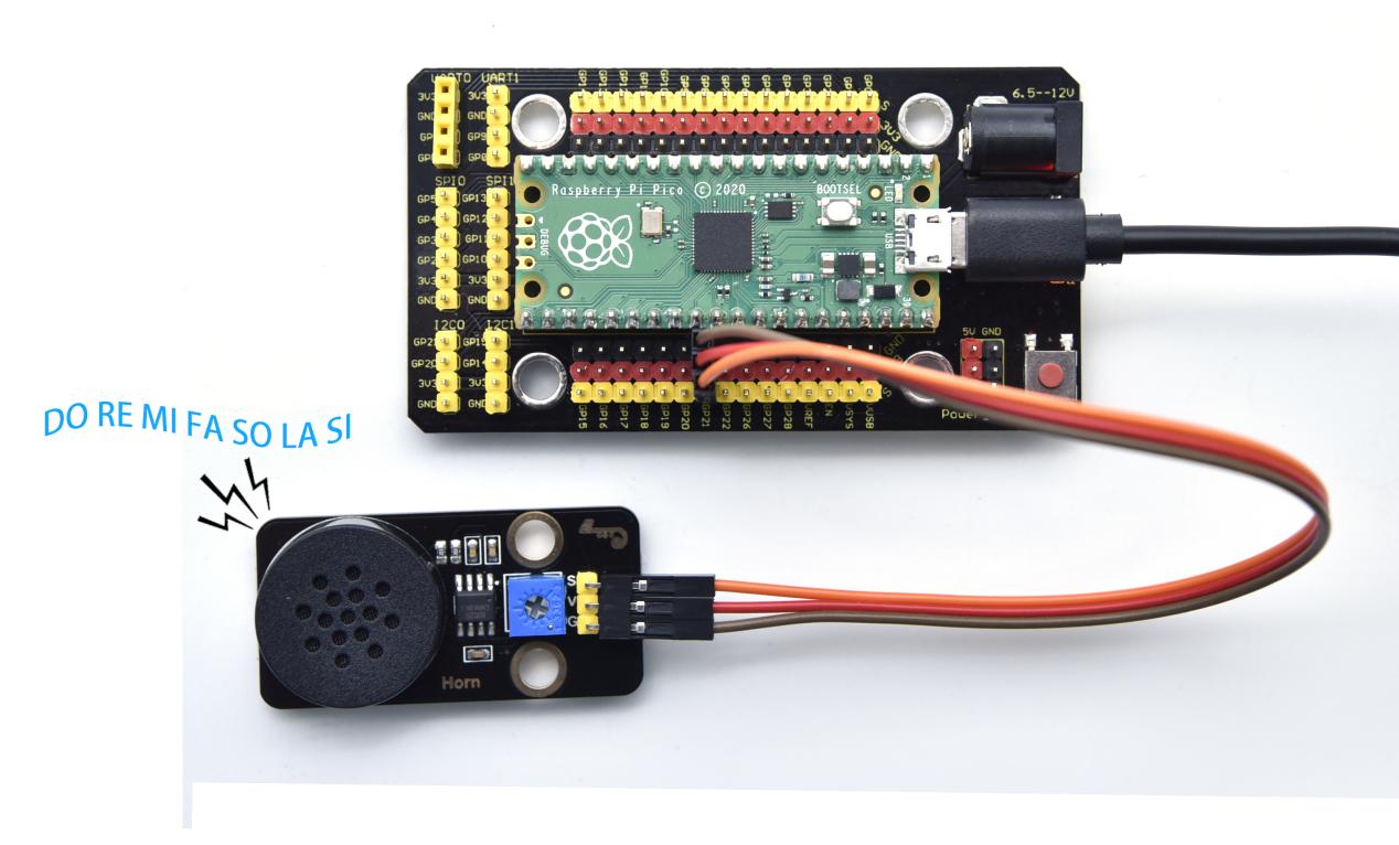
Connection Diagram
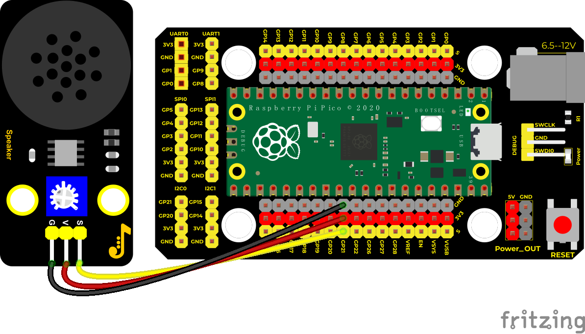
Run the test code
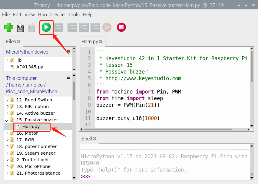
Find and double-click Horn.py to open it, then click to run the code.
Code Explanation
In this experiment, we use the PWM class of the machine module, buzzer = PWM(Pin(21)) to create an instance of the PWM class, and the buzzer pin is connected to GP21.
The buzzer.duty_u16(1000): set the duty cycle, and the duty cycle is 1000/65535. The larger the value, the louder the buzzer. When set to 0, the buzzer does not emit sound. buzzer.freq() is the frequency setting method.
In the experiment, we use the PWM on the machine module. buzzer = PWM(Pin(21))
Test Result
Upload the test code successfully and power on. The power amplifier module will emit the sound of the corresponding frequency corresponding to the beat:
DO for 0.5s, Re for 0.5s, Mi for 0.5s, Fa for 0.5s, So for 0.5s, La 0.5s and Si for 0.5s
Test Code
'''
 * * Keyestudio 42 in 1 Starter Kit for Raspberry Pi Pico
 * lesson 15
 * Passive buzzer
 * http://www.keyestudio.com
'''
from machine import Pin, PWM
from time import sleep
buzzer = PWM(Pin(21))

buzzer.duty_u16(1000)

buzzer.freq(523)#DO
sleep(0.5)
buzzer.freq(586)#RE
sleep(0.5)
buzzer.freq(658)#MI
sleep(0.5)
buzzer.freq(697)#FA
sleep(0.5)
buzzer.freq(783)#SO
sleep(0.5)
buzzer.freq(879)#LA
sleep(0.5)
buzzer.freq(987)#SI
sleep(0.5)
buzzer.duty_u16(0)
Project 16: 130 Motor

Description
The 130 motor driver module is compatible with servo motors, which has high efficiency and good quality fans.
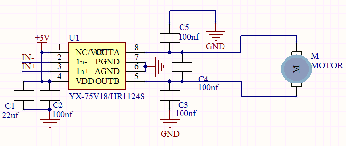
It adopts a HR1124S motor control chip. HR1124S is a single-channel H-bridge driver chip for DC motor solutions. In addition, this chip has low standby current and low quiescent current.
The module is compatible with various single-chip control boards. In the experiment, we can control the rotation direction of the motor by outputting the voltage directions of the two signal terminals IN+ and IN- to make the motor rotate.
Working Principle
The chip is used to help drive the motor.
We can’t drive it with a triode or an IO port due to its a large current of need. It is very simple to make the motor rotate. Just apply voltage to both ends of the motor. The direction of the motor is different in different voltage directions. Within the rated voltage, the higher the voltage, the faster the motor rotates; on the contrary, the lower the voltage, the slower the motor rotates, or even unable to rotate.
So we can use the PWM port to control the speed of the motor. We haven’t learned PWM here, so we use the high and low levels to control the motor first.
Required Components
|
|
|
|---|---|---|
Raspberry Pi Pico Board*1 |
Raspberry Pi Pico Expansion Board*1 |
keyestudio DIY 130 Motor*1 |
|
|
|
4P Dupont Wire*1 |
Micro USB Cable*1 |
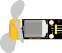
Note: the motor is separated with its fan, you need to assemble it first.
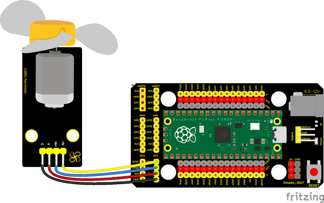
Connection Diagram
Run the test code
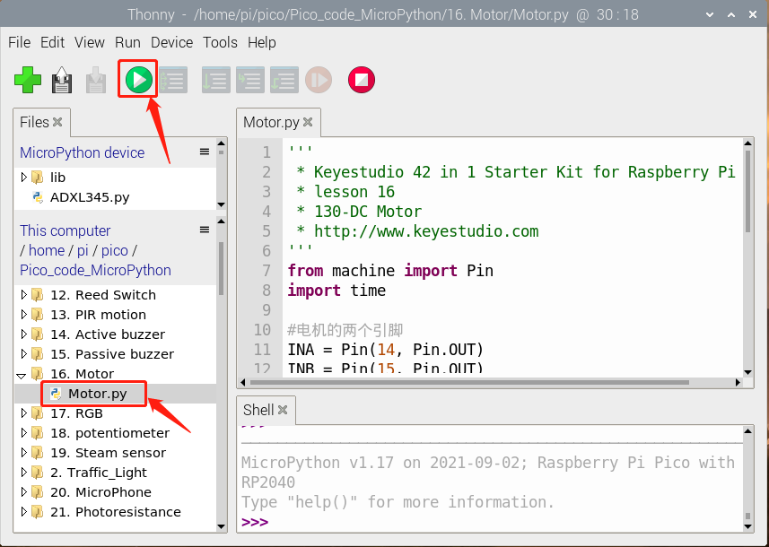
Find Motor.py,double-click and click
Code Explanation
Set pins to 14 and 15, when the pin 14 outputs high levels and the pin 15 outputs low levels, the motor will rotate counterclockwise; when both pins are set to low, the motor stops rotating.
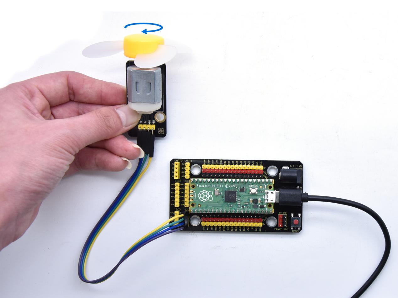
Test Result
Wire up, upload test code and test the 130 motor, the fan will rotate counterclockwise for 2 seconds, stop for 1 second; and rotate clockwise for 2 seconds and stop for 1 second; cycle alternately.
Test Code
'''
 * * Keyestudio 42 in 1 Starter Kit for Raspberry Pi Pico
 * lesson 16
 * 130-DC Motor
 * http://www.keyestudio.com
'''
from machine import Pin
import time

#two pins of the motor
INA = Pin(14, Pin.OUT)
INB = Pin(15, Pin.OUT)

while True:
    #turn anticlockwise for 2s
    INA.value(1)
    INB.value(0)
    time.sleep(2)
    #stop 1s
    INA.value(0)
    INB.value(0)
    time.sleep(1)
    #turn clockwise for 2s
    INA.value(0)
    INB.value(1)
    time.sleep(2)
    #stop 1s
    INA.value(0)
    INB.value(0)
    time.sleep(1)
Project 17: RGB Module

Overview
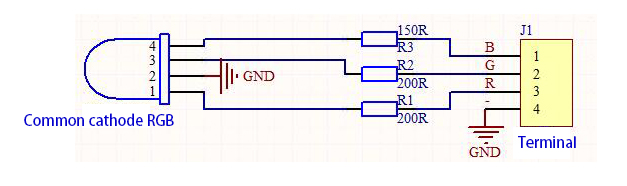
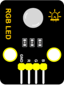
Among these modules is a RGB module. It adopts a F10-full color RGB foggy common cathode LED. We connect the RGB module to the PWM port of MCU and the other pin to GND(for common anode RGB, the rest pin will be connected to VCC). So what is PWM?
PWM is a means of controlling the analog output via digital means. Digital control is used to generate square waves with different duty cycles (a signal that constantly switches between high and low levels) to control the analog output.In general, the input voltages of ports are 0V and 5V. What if the 3V is required? Or a switch among 1V, 3V and 3.5V? We cannot change resistors constantly. For this reason, we resort to PWM.
For Arduino digital port voltage outputs, there are only LOW and HIGH levels, which correspond to the voltage outputs of 0V and 5V respectively. You can define LOW as“0”and HIGH as“1’, and let the Arduino output five hundred‘0’or“1”within 1 second. If output five hundred‘1’, that is 5V; if all of which is‘0’,that is 0V; if output 250 01 pattern, that is 2.5V.
This process can be likened to showing a movie. The movie we watch are not completely continuous. Actually, it generates 25 pictures per second, which cannot be told by human eyes. Therefore, we mistake it as a continuous process. PWM works in the same way. To output different voltages, we need to control the ratio of 0 and 1. The more‘0’or‘1’ output per unit time, the more accurate the control.
Working Principle
For our experiment, we will control the RGB module to display different colors through three PWM values.
Components
|
|
|
|---|---|---|
Raspberry Pi Pico Board*1 |
Raspberry Pi Pico Expansion Board*1 |
Keyestudio Common Cathode RGB Module *1 |
|
|
|
4P Dupont Wire*1 |
Micro USB Cable*1 |
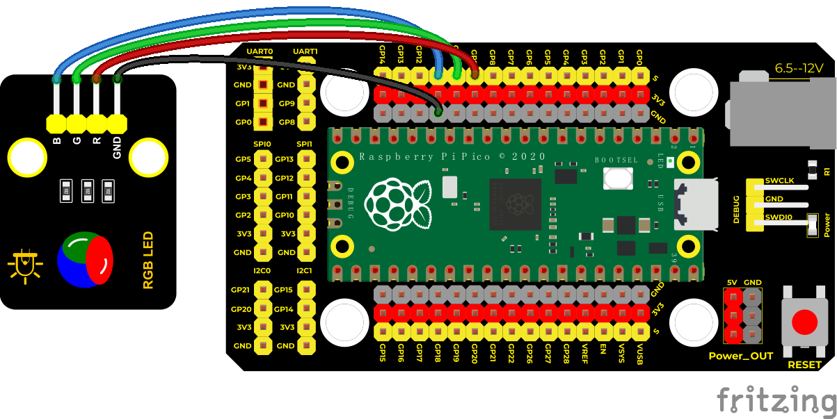
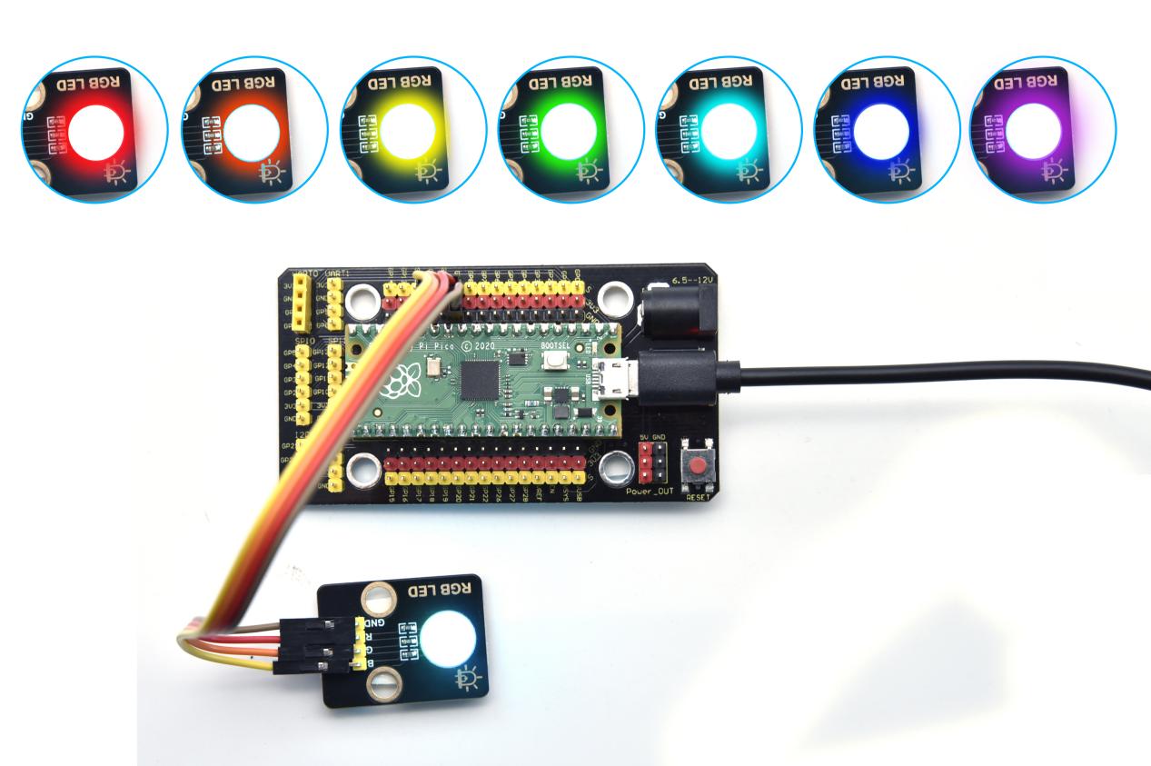
Connection Diagram
Run the test code
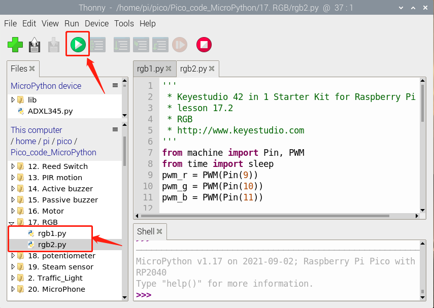
Find rgb1.py and rgb2.py,double-click and click
Code 1:
'''
 * * Keyestudio 42 in 1 Starter Kit for Raspberry Pi Pico
 * lesson 17.1
 * RGB
 * http://www.keyestudio.com
'''
from machine import Pin
from time import sleep

red = Pin(9, Pin.OUT)
green = Pin(10, Pin.OUT)
blue = Pin(11, Pin.OUT)

while 1:
    red.value(1)
    green.value(0)
    blue.value(0)
    sleep(1)
    red.value(0)
    green.value(1)
    blue.value(0)
    sleep(1)
    red.value(0)
    green.value(0)
    blue.value(1)
    sleep(1)
Code 2:
'''
 * * Keyestudio 42 in 1 Starter Kit for Raspberry Pi Pico
 * lesson 17.2
 * RGB
 * http://www.keyestudio.com
'''
from machine import Pin, PWM
from time import sleep
pwm_r = PWM(Pin(9))
pwm_g = PWM(Pin(10))
pwm_b = PWM(Pin(11))

pwm_r.freq(1000)
pwm_g.freq(1000)
pwm_b.freq(1000)

def light(red, green, blue):
    pwm_r.duty_u16(red)
    pwm_g.duty_u16(green)
    pwm_b.duty_u16(blue)

while 1:
    light(65535, 0, 0)#red
    sleep(1)
    light(65535, 25088, 0)#orange
    sleep(1)
    light(65535, 65535, 0)#yellow
    sleep(1)
    light(0, 65535, 0)#green
    sleep(1)
    light(0, 0, 65535)#blue
    sleep(1)
    light(0, 65535, 65535)#cyanogen
    sleep(1)
    light(41216, 8448, 61696)#purple
    sleep(1)
Explanation
Code 1:
In the code 1, red, green and blue represent the red, green and blue ports. According to the wiring diagram, we have connected to GP9, GP10 and GP11,then set to 9, 10 and 11.Use the function .value(1) to set three LEDs.If the corresponding digital port is high level, and the corresponding LED will be on
The RGB module displays red color for 1 second, green color for 1 second, and blue color for 1 second, cycle alternately.
Code 2:
In the code 2, we use PWM output, and set frequency to .freq(1000).duty_u16()
The number in the brackets means the proportion of the color of LED. The larger the duty cycle data we set, the larger the proportion of the color.
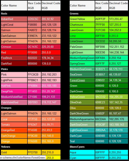
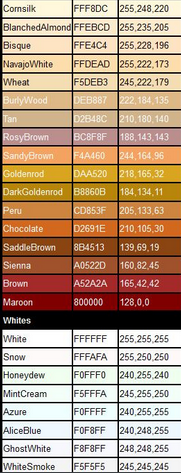
(Note: the duty cycle above we set is maximum to .duty_u16(65535), this value is 256*256 - 1, that is 0~65535. As for the following the RGB color table, you only need to make values below multiply by 256.
In the experiment, we adjust the ratio of red, green and blue colors on the RGB LED by setting the corresponding values, so as to control the RGB LED to display corresponding colors. So theoretically, there are 256*256*256 colors that can be set (for details, please refer to the common RGB color table below)
RGB Color Chart
Test Result
Upload the code 1, the RGB on the module will show red, green and blue color with an interval of 1s.
Upload the code 2, the RGB on the module will show red, orange, yellow, green, cyan-blue, blue, purple and white color with an interval of 1s.
Project 18: Potentiometer

Overview
The following we will introduce is the Keyestudio rotary potentiometer which is an analog sensor.
The digital IO ports can read the voltage value between 0 and 3.3V and the module only outputs high levels. However, the analog sensor can read the voltage value through ADC analog ports(GP26~GP28) on the pico board.
In the experiment, we will display the test results on the Shell.
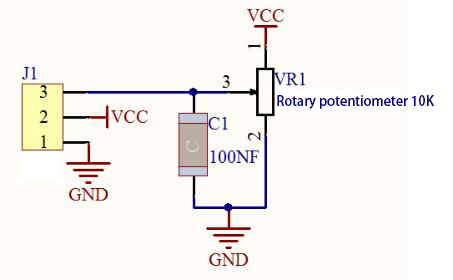
Working Principle
It uses a 10K adjustable resistor. We can change the resistance by rotating the potentiometer. The signal S can detect the voltage changes(0-3.3V) which are analog quantity
Components
|
|
|
|---|---|---|
Raspberry Pi Pico Board*1 |
Raspberry Pi Pico Expansion Board*1 |
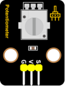
Keyestudio Rotary Potentiometer*1 |
|
|
|
3P Dupont Wire*1 |
Micro USB Cable*1 |
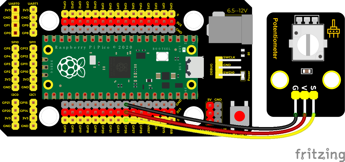
Connection Diagram
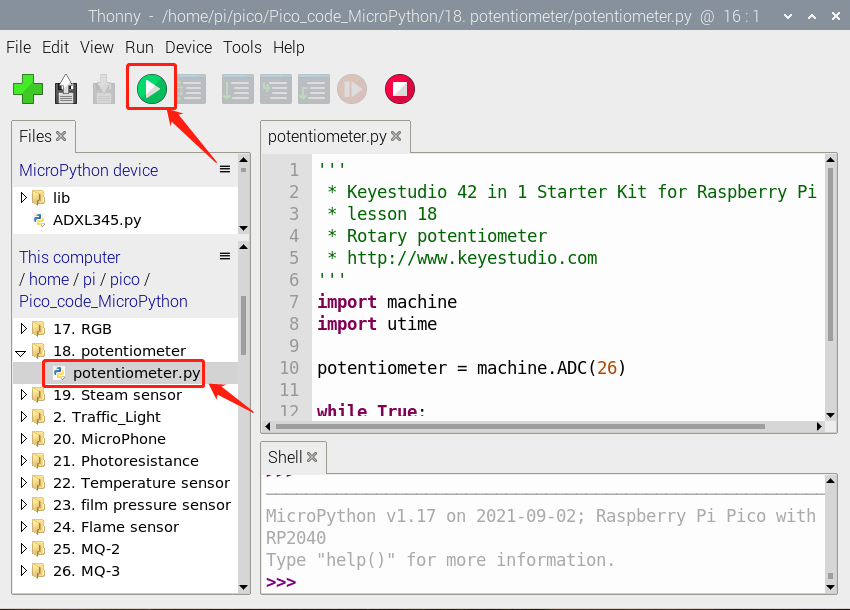
Run the Test Code
Find and double-click potentiometer.py to open it, then click to run the code.
Test Code
'''
 * * Keyestudio 42 in 1 Starter Kit for Raspberry Pi Pico
 * lesson 18
 * Rotary potentiometer
 * http://www.keyestudio.com
'''
import machine
import utime

potentiometer = machine.ADC(26)

while True:
    pot_value = potentiometer.read_u16()
    print(pot_value)
    utime.sleep(0.1)
Code Explanation
In the experiment, we will create ADC example, connect GP26 ADC(26). That means ADC(0).
.read_u16() is used to read analog values, in the range of 0~65535.
potentiometer.read_u16() means that reading the analog value of ADC(26) pin then assign it to the variable pot_value
utime.sleep() is the delay function which works as same as the function time.sleep()
analogVal means analog value. The rotary potentiometer outputs analog values(0~4095), therefore, we set pins to analog ports. For example, we connect to ADC0(GP26)
analogRead(pin): read the value of the specified analog pin. The pico board contains a multi-channel, 12-bit converter. This means that it will map the input voltage between 0 and the working voltage (5V or 3.3V) to an integer value between 0 and 4095. For example, this will produce a resolution among readings: 3.3V/4096 stands for 0.0008V per unit.
Pin: the name of analog input pin. GP26 is connected to GP28, GP29 measures VSYS voltage and ADC4 measures the internal temperature.
Test Result
Run the test code, observe the analog value in the Shell monitor. In the experiment , run the test code then observe the analog value. Rotate the knob of the potentiometer clockwise to increase the analog value. On the contrary, the analog value will be reduced by rotating the potentiometer anticlockwise. The value is in the range of 0-65535.
Upload the code power up by a USB cable, open the serial monitor and set baud rate to 9600. In the experiment, rotate the potentiometer clockwise, the analog value increases, and turn the potentiometer counterclockwise, the analog value decreases(0-4095), as shown in the figure below.
Project 19: Steam Sensor

Description
This is a commonly used steam sensor. Its principle is to detect the amount of water by bare printed parallel lines on the circuit board. The more the water is, the more wires will be connected. As the conductive contact area increases, the output voltage will gradually rise. It can detect water vapor in the air as well. The steam sensor can be used as a rain water detector and level switch. When the humidity on the sensor surface surges, the output voltage will increase.
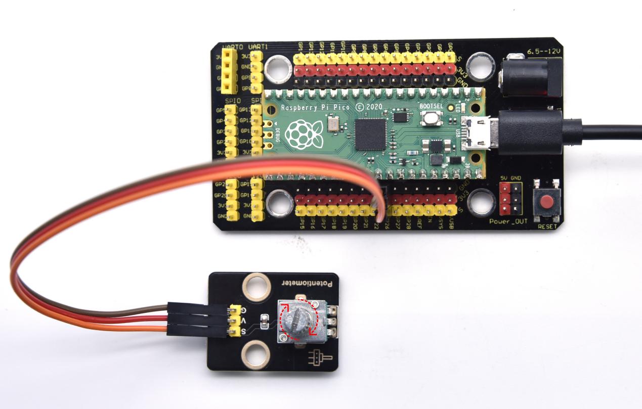
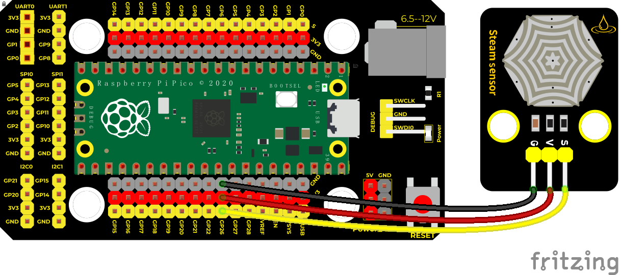
In the experiment, we connect the signal terminal (S terminal) of the sensor to the analog port of the pico development board. The analog value detected will be displayed on the serial monitor.
This is a DIY electronic building block water drop sensor. It is an analog (digital) input module, also called rain, rain sensor. It can be used to monitor various weather conditions, detect whether it is raining and the amount of rain, convert it into digital signal (DO) and analog signal (AO) output, and is widely used in Arduino robot kits, raindrops, rain sensors, and can be used for various It can monitor various weather conditions, and convert it into digital signal and AO output, and can also be used for automobile automatic wiper system, intelligent lighting system and intelligent sunroof system. In the experiment, we input the sensor signal terminal (S terminal) to the analog port of the pico development board, sense the change of the analog value, and display the corresponding analog value on the shell.
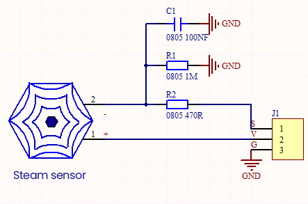
Its principle is to detect the amount of water through the exposed printed parallel lines on the circuit board. The more water there is, the more wires will be connected, and the conductive contact area increases. The voltage output by pin 2 will gradually increase. The larger the analog value detected by the signal terminal S is.
It can also detect steam in the air. Two position holes are used to install on the other devices.
Required Components
|
|
|
|---|---|---|
Raspberry Pi Pico Board*1 |
Raspberry Pi Pico Expansion Board*1 |
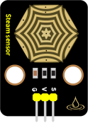
Keyestudio DIY Steam Sensor *1 |
|
|
|
3P Dupont Wire*1 |
Micro USB Cable*1 |
Connection Diagram
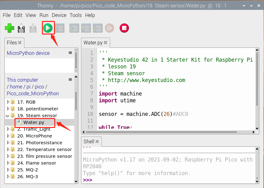
Run the test code
Find Water.py,double-click and click
Test Code
'''
 * * Keyestudio 42 in 1 Starter Kit for Raspberry Pi Pico
 * lesson 19
 * Steam sensor
 * http://www.keyestudio.com
'''
import machine
import utime

sensor = machine.ADC(26)#ADC0

while True:
    value = sensor.read_u16()
    print(value)
    utime.sleep(0.1)
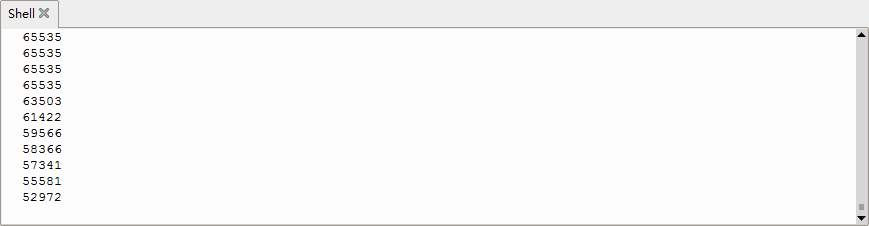
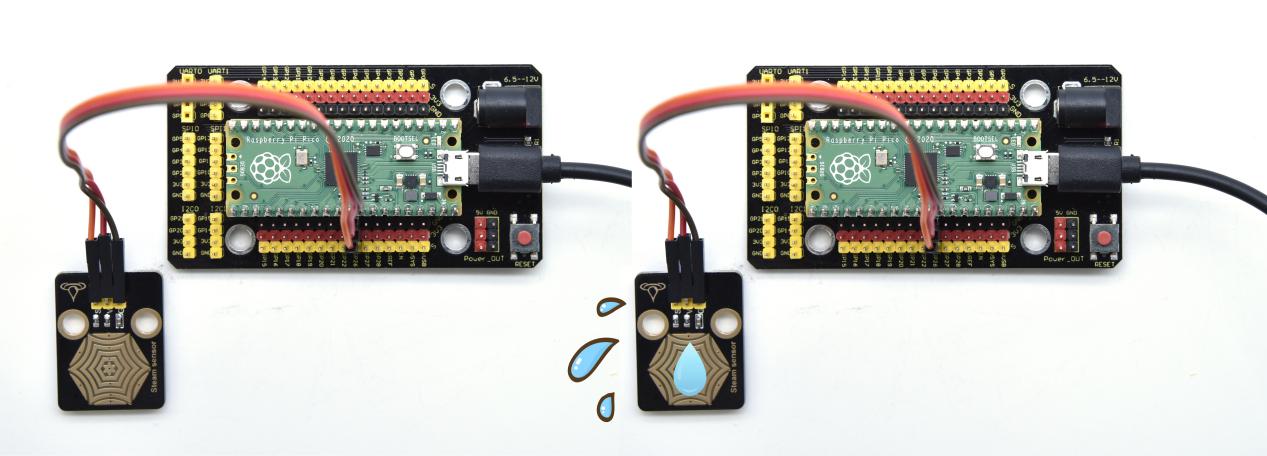
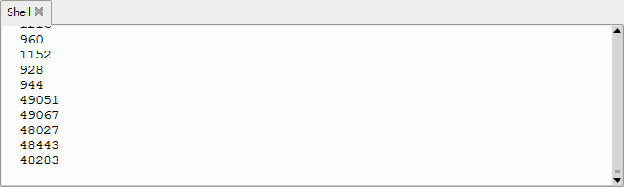
Test Result
Wire up, run the test code, then the output analog value is displayed in the shell. The more water volume, the greater the output voltage and the analog value, as shown below.
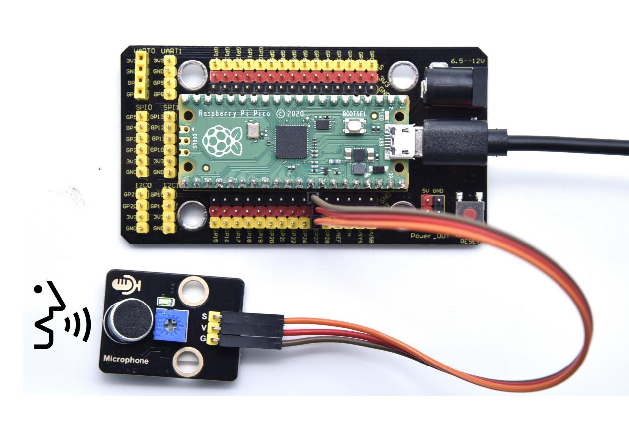
Project 20: Sound Sensor

Overview
In this kit, there is a sound sensor. In the experiment, we test the analog value corresponding to the sound level in the current environment with it. The louder the sound, the larger the analog value.
Working Principle
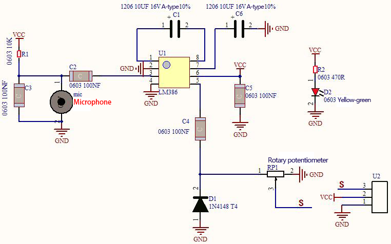
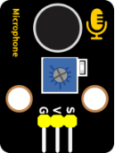
It uses a high-sensitive microphone component and an LM386 chip.
We build the circuit with the LM386 chip and amplify the sound through the high-sensitive microphone. In addition, we can adjust the sound volume by the potentiometer. Rotate it clockwise, the sound will get louder.
Components
|
|
|
|---|---|---|
Raspberry Pi Pico Board*1 |
Raspberry Pi Pico Expansion Board*1 |
Keyestudio DIY Sound Sensor*1 |
|
|
|
3P Dupont Wire*1 |
Micro USB Cable*1 |
Connection Diagram
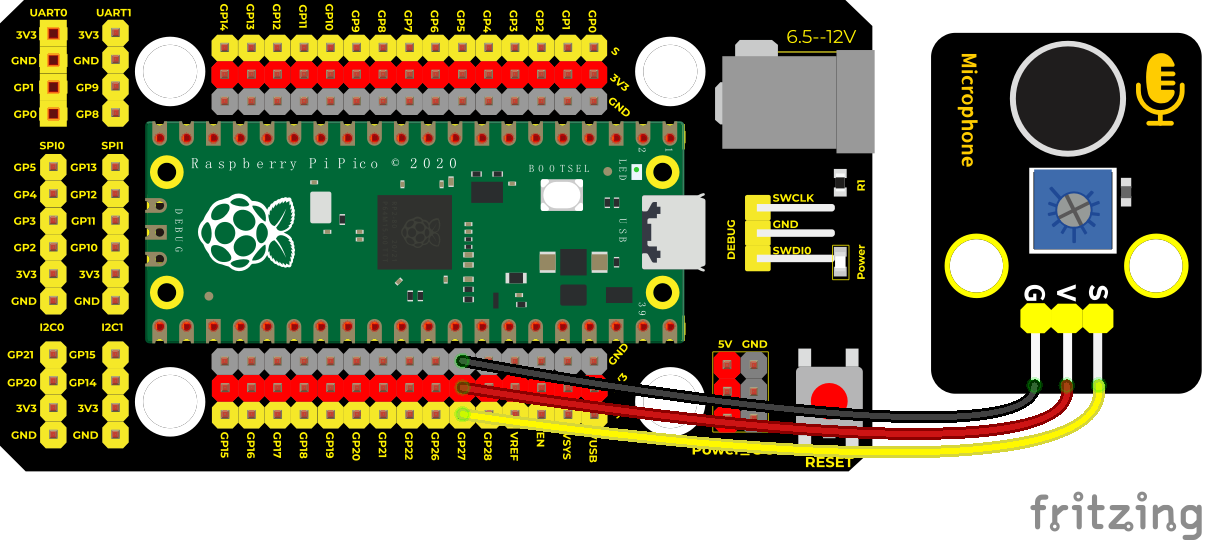
Run the test code
Find MicroPhone.py,double-click and click
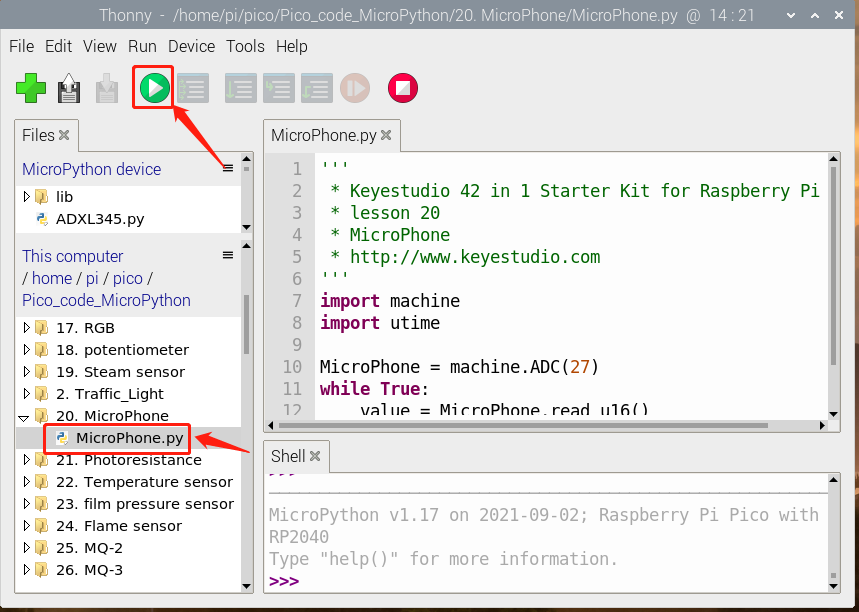
Test Code
'''
 * * Keyestudio 42 in 1 Starter Kit for Raspberry Pi Pico
 * lesson 20
 * MicroPhone
 * http://www.keyestudio.com
'''
import machine
import utime

MicroPhone = machine.ADC(27)
while True:
    value = MicroPhone.read_u16()
    print(value)
    utime.sleep(0.1)
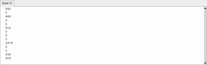
Test Result
Upload the code and observe the analog value on the Shell monitor. Rotate clockwise the potentiometer and speak at the MIC. Then you can see the analog value get larger, as shown below
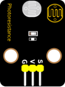
Project 21: Photoresistor
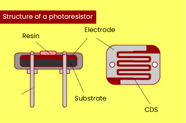
Description
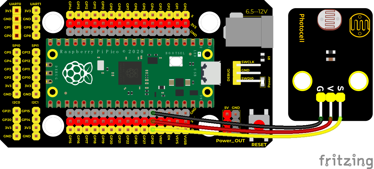
In this kit, there is a photoresistor which consists of photosensitive resistance elements. Its resistance changes with the light intensity. Also, it converts the resistance change into a voltage change through the characteristic of the photosensitive resistive element. When wiring it up, we interface its signal terminal (S terminal) with the analog port of pico , so as to sense the change of the analog value, and display the corresponding analog value in the shell.
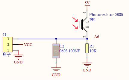
Working Principle
If there is no light, the resistance is 0.2MΩ and the detected voltage at the terminal 2 is close to 0. When the light intensity increases, the resistance of photoresistor and detected voltage will diminish.
Components
|
|
|
|---|---|---|
Raspberry Pi Pico Board*1 |
Raspberry Pi Pico Expansion Board*1 |
Keyestudio DIY Photoresistor*1 |
|
|
|
3P Dupont Wire*1 |
Micro USB Cable*1 |
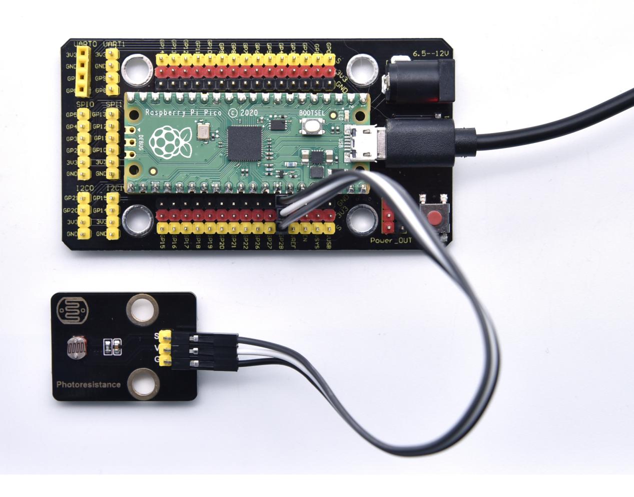
Connection Diagram
Run the test code
Find photoresistance.py to double-click and click.
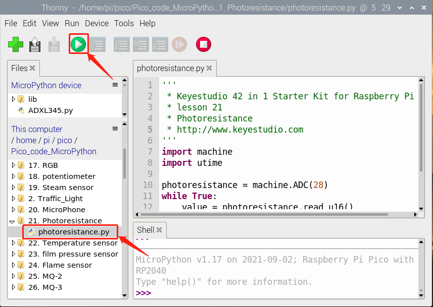
Test Code
'''
 * * Keyestudio 42 in 1 Starter Kit for Raspberry Pi Pico
 * lesson 21
 * Photoresistance
 * http://www.keyestudio.com
'''
import machine
import utime

photoresistance = machine.ADC(28)
while True:
    value = photoresistance.read_u16()
    print(value)
    utime.sleep(0.1)
Test Result
Wire up, run the test code, observe the Shell monitor. Then you will view the analog value of the light intensity. The brighter the light, the greater the analog value.
Project 22: NTC-MF52AT Thermistor

Overview
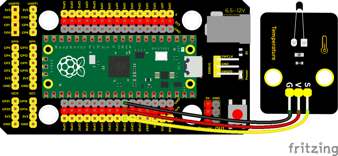
In the experiment, there is a NTC-MF52AT analog thermistor. We connect its signal terminal to the analog port of the Raspberry Pi Pico Board and read the corresponding analog value.
We can use analog values to calculate the temperature of the current environment through specific formulas. Since the temperature calculation formula is more complicated, we only read the corresponding analog value.
Working Principle
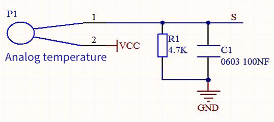
This module mainly uses NTC-MF52AT thermistor elements. The NTC-MF52AT thermistor element can sense the changes of the surrounding environment temperature. Resistance changes with the temperature, causing the voltage of the signal terminal S to change. This sensor uses the characteristics of NTC-MF52AT thermistor element to convert resistance changes into voltage changes.
Components
|
|
|
|---|---|---|
Raspberry Pi Pico Board*1 |
Raspberry Pi Pico Expansion Board*1 |
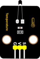
Keyestudio NTC-MF52AT Thermistor*1 |
|
|
|
3P Dupont Wire*1 |
Micro USB Cable*1 |
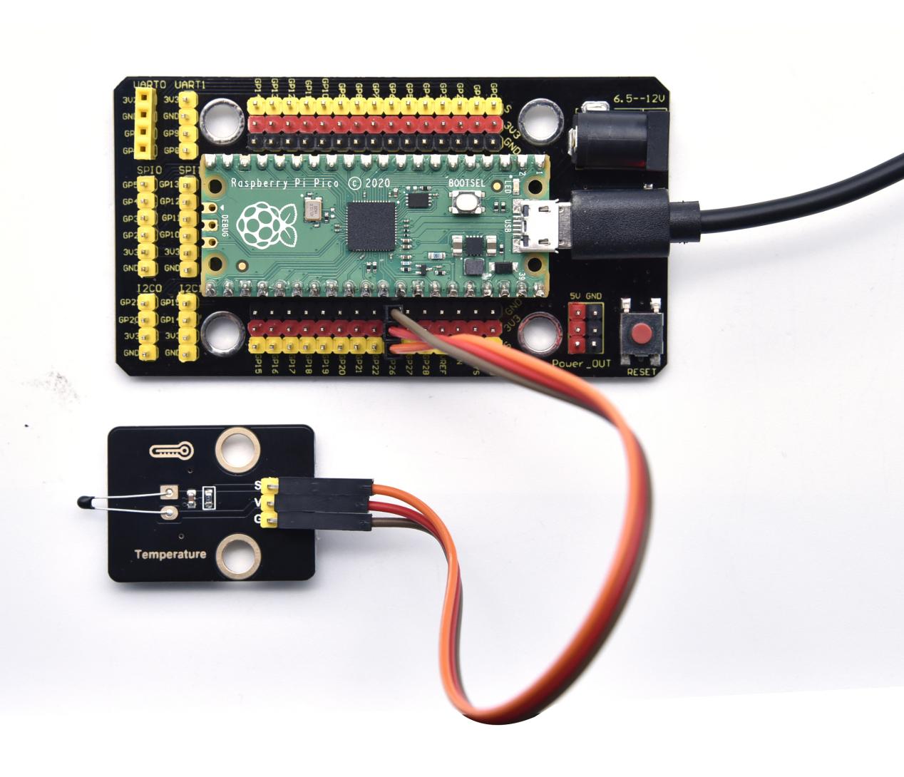
Connection Diagram
Run the test code
Find and double-click temperature.py and click
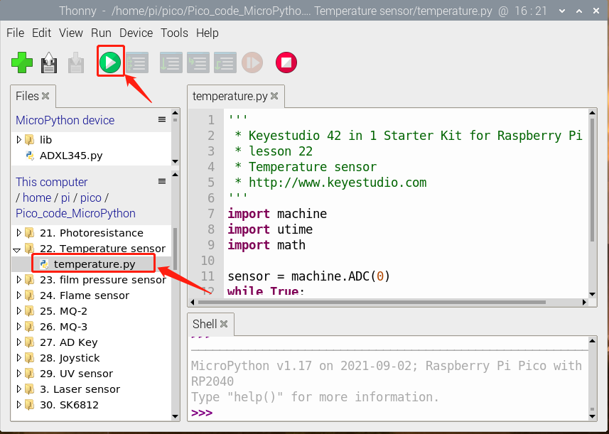
Test Code
'''
 * * Keyestudio 42 in 1 Starter Kit for Raspberry Pi Pico
 * lesson 22
 * Temperature sensor
 * http://www.keyestudio.com
'''
import machine
import utime
import math

sensor = machine.ADC(0)
while True:
    temp = sensor.read_u16()
    print("Temperature ADC: ", end = " ")
    print(temp)
    utime.sleep(0.1)
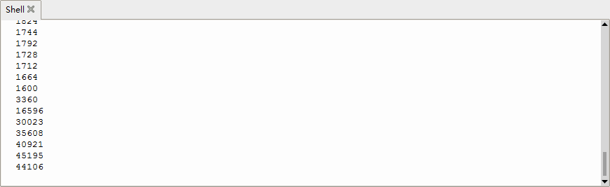
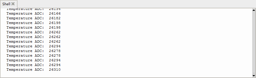
Test Result
Upload the code and observe the Shell monitor. The higher the temperature, the larger the analog value.
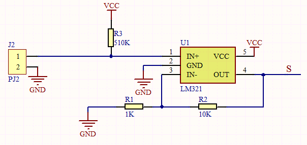
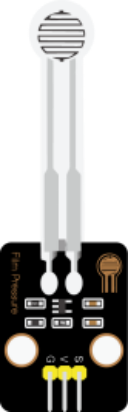
Project 23: Thin-film Pressure Sensor
Overview
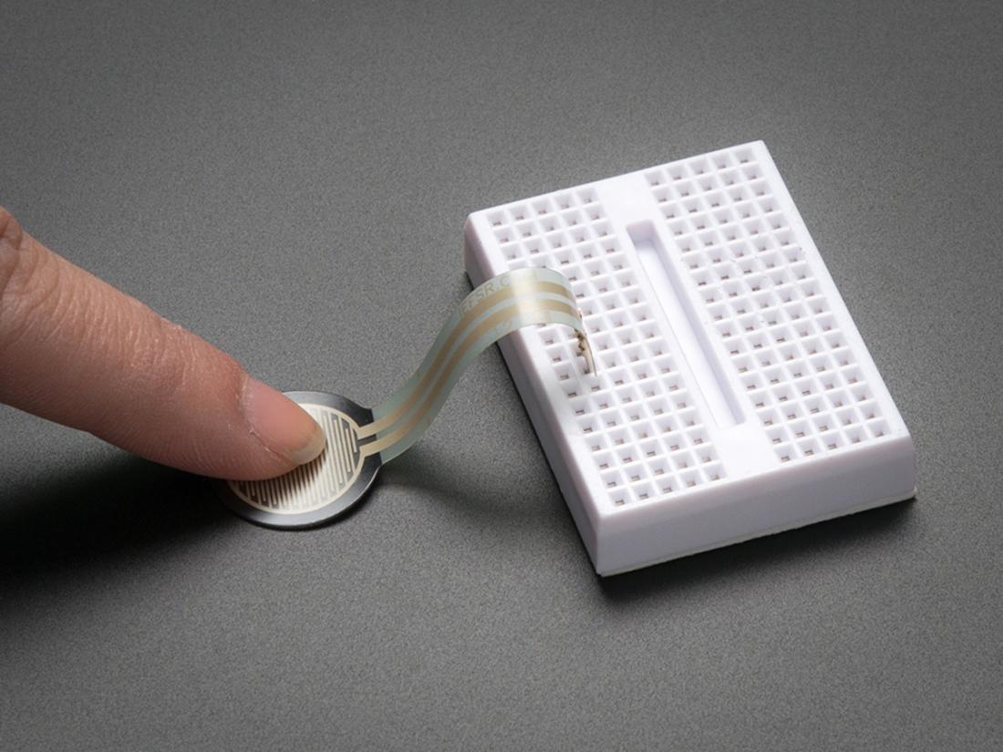
In this kit, there is a Keyestudio thin-film pressure sensor. The thin-film pressure sensor composed of a new type of nano pressure-sensitive material and a comfortable ultra-thin film substrate, has waterproof and pressure-sensitive functions.
In the experiment, we determine the pressure by collecting the analog signal on the S end of the module. The smaller the analog value, the greater the pressure; and the displayed results will shown on the Shell.
Working Principle
When the sensor is pressed by external forces, the resistance value of sensor will vary. We convert the pressure signals detected by the sensor into the electric signals through a circuit. Then we can obtain the pressure changes by detecting voltage signal changes.
Components
|
|
|
|---|---|---|
Raspberry Pi Pico Board*1 |
Raspberry Pi Pico Expansion Board*1 |
KeyestudioThin-film Pressure Sensor*1 |
|
|
|
3P Dupont Wire*1 |
Micro USB Cable*1 |
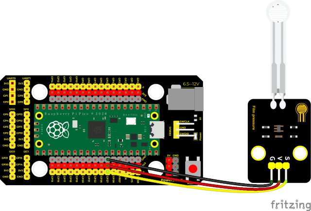
Connection Diagram
Run the test code
Find the film pressure.py open it and click.
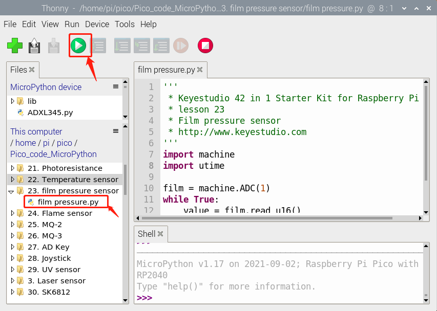
Test Code
'''
 * * Keyestudio 42 in 1 Starter Kit for Raspberry Pi Pico
 * lesson 23
 * Film pressure sensor
 * http://www.keyestudio.com
'''
import machine
import utime

film = machine.ADC(1)
while True:
    value = film.read_u16()
    print(value)
    utime.sleep(0.1)
Test Result
Upload the code and observe the Shell monitor. When the thin-film is pressed by fingers, the analog value will decrease, as shown below.
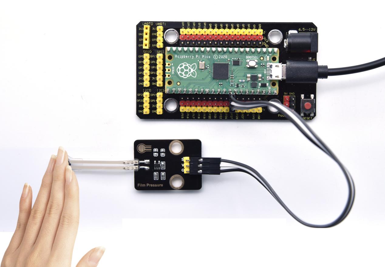
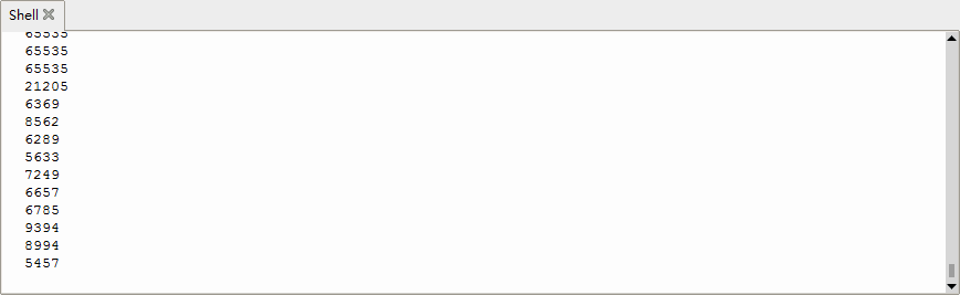
Project 24: Flame Sensor

Description
In daily life, it is often seen that a fire broke out without any precaution. It will cause great economic and human loss. So how can we avoid this situation? Right, install a flame sensor and a speaker in those places that easily break out a fire. When the flame sensor detects a fire, the speaker will alarm people quickly to put out the fire.
So in this project, you will learn how to use a flame sensor and an active buzzer module to simulate the fire alarm system.
Working Principle
This flame sensor can be used to detect fire or other light sources with wavelength stands at 760nm ~ 1100nm. Its detection angle is about 60°. You can rotate the potentiometer on the sensor to control its sensitivity. Adjust the potentiometer to make the LED at the critical point between on and off state. The sensitivity is the best.
From the below figure, power up. When detecting fire, the digital pin outputs low levels, the red LED2 will light up first, the digital signal terminal D0 outputs a low level, and the red LED1 will light up. The stronger the external infrared light, the smaller the value; the weaker the infrared light, the larger the value.
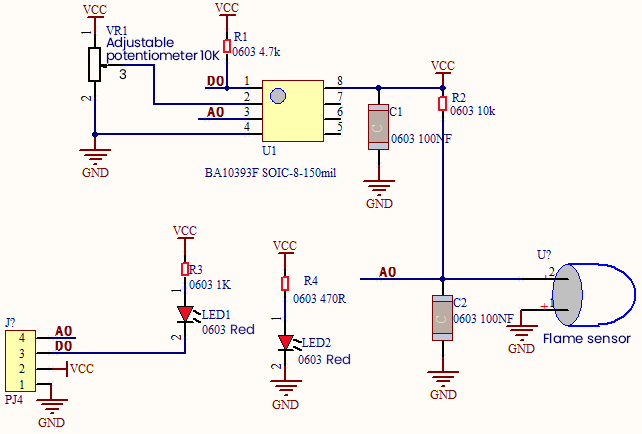
Required Components
|
|
|
|---|---|---|
Raspberry Pi Pico Board*1 |
Raspberry Pi Pico Expansion Board*1 |
keyestudio DIY Flame Sensor*1 |
|
|
|
4P Dupont Wire*1 |
Micro USB Cable*1 |
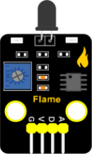
Connection Diagram
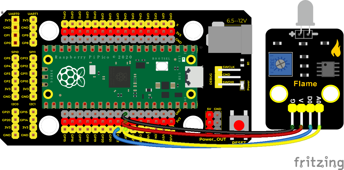
Run the test code
Find and double-click Flame_sensor.py and click
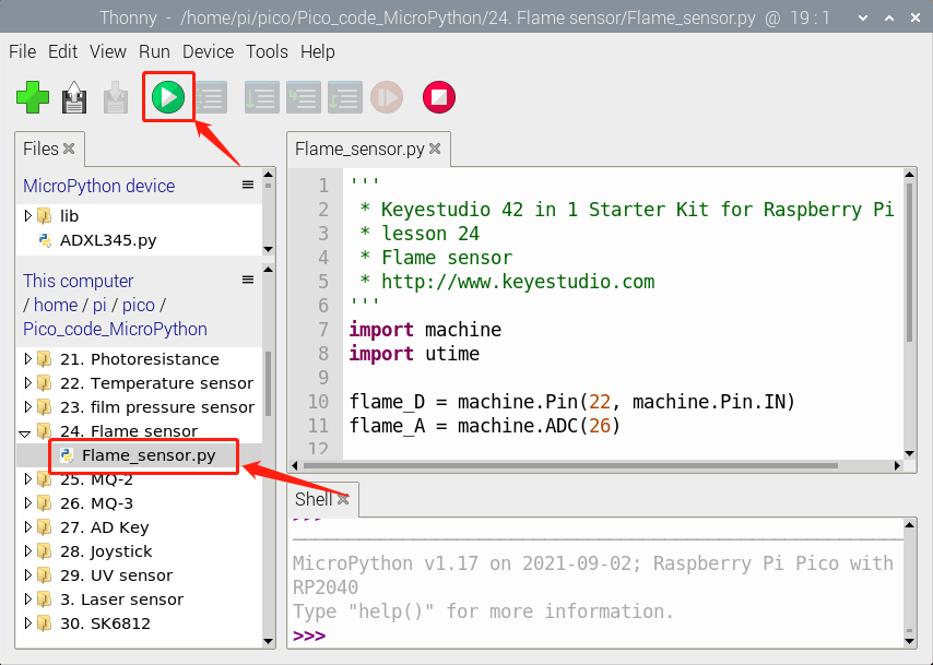
Test Code
'''
 * * Keyestudio 42 in 1 Starter Kit for Raspberry Pi Pico
 * lesson 24
 * Flame sensor
 * http://www.keyestudio.com
'''
import machine
import utime

flame_D = machine.Pin(22, machine.Pin.IN)
flame_A = machine.ADC(26)

while True:
    digitalVal = flame_D.value()
    analogVal = flame_A.read_u16()
    print(digitalVal, end = "  ")
    print(analogVal)
    utime.sleep(0.1)
Code Explanation
Two pins we use are defined as 22 and 26 according to the wiring-up diagram, and print digital signals and analog signals respectively.
Test Result
Upload the test code and power up,LED2 is on and LED1 is off. Open the monitor and set baud rate to 9600. When fire is detected, LED1 will be on. the digital value will change from 1 to 0, and the analog value will become smaller, as shown in the figure below.
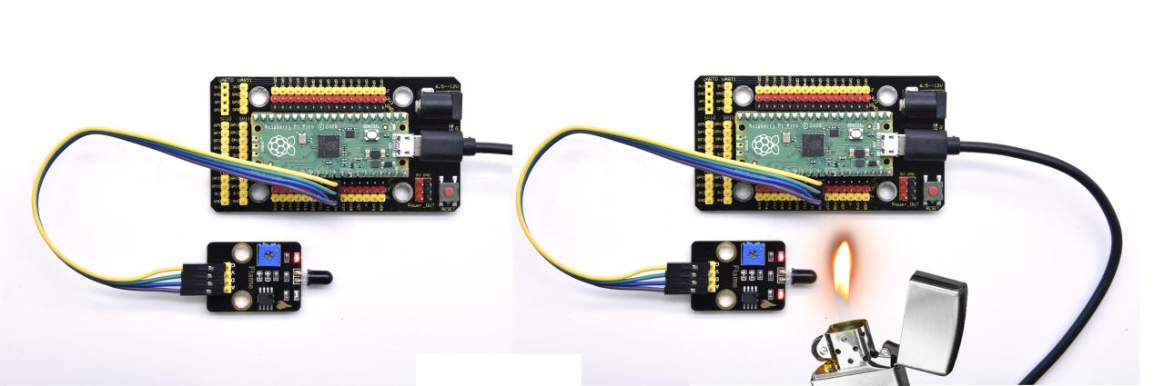
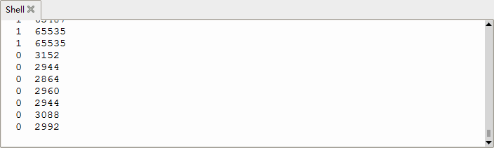
Project 25: MQ-2 Gas Sensor

Description
This analog gas sensor - MQ2 is used in gas leakage detecting equipment in consumer electronics and industrial markets.
This sensor is suitable for detecting LPG, I-butane, propane, methane, alcohol, Hydrogen and smoke. It has high sensitivity and quick response.
In addition, the sensitivity can be adjusted by rotating the potentiometer.
In the experiment, we read the analog value at the A0 port and the D0 port to determine the content of gas.
Working Principle
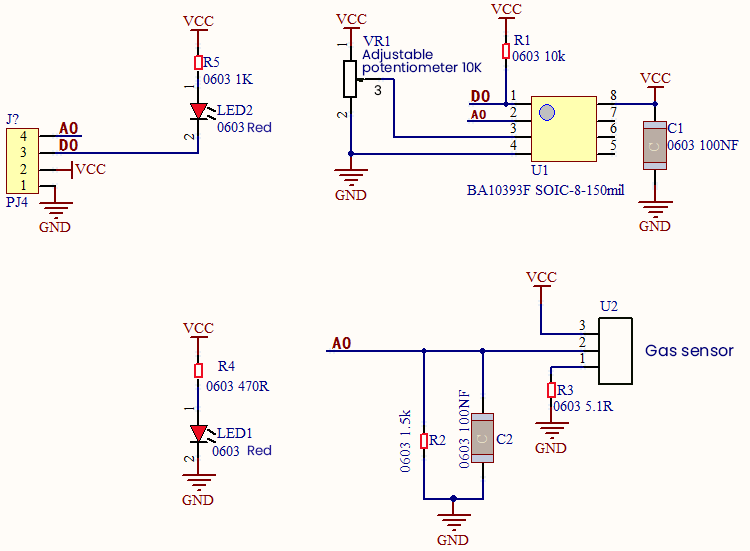
The greater the concentration of smoke, the greater the conductivity, the lower the output resistance, the greater the output analog signal.
When in use, the A0 terminal reads the analog value of the corresponding gas; the D0 terminal is connected to an LM393 chip (voltage comparator), we can adjust the alarm threshold of the measured gas through the potentiometer, and output the digital value at D0. When the measured gas content exceeds the critical point, the D0 terminal outputs a low level; when the measured gas content does not exceed the critical point, the D0 terminal outputs a high level.
Required Components
|
|
|
|---|---|---|
Raspberry Pi Pico Board*1 |
Raspberry Pi Pico Expansion Board*1 |
keyestudio DIY Analog Gas Sensor*1 |
|
|
|
4P Dupont Wire*1 |
Micro USB Cable*1 |
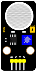
Connection Diagram
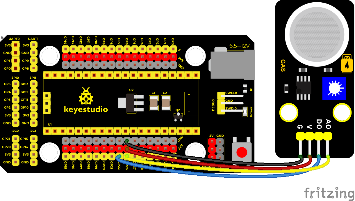
Run the test code
Find and double-click MQ-2.py and click
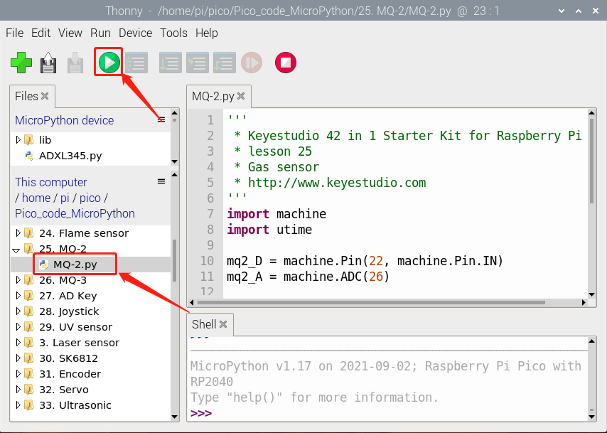
Test Code
'''
 * * Keyestudio 42 in 1 Starter Kit for Raspberry Pi Pico
 * lesson 25
 * Gas sensor
 * http://www.keyestudio.com
'''
import machine
import utime

mq2_D = machine.Pin(22, machine.Pin.IN)
mq2_A = machine.ADC(26)

while True:
    digitalVal = mq2_D.value()
    analogVal = mq2_A.read_u16()
    print(digitalVal, end = "  ")
    print(analogVal, end = "  ")
    if digitalVal == 0:
        print("Exceeding")
    else:
        print("Normal")
    utime.sleep(0.1)
Test Result
Run the test code, the yellow-green LED on the module lights up, observe the shell, and display the corresponding data and characters.
In the experiment, we can see that when the simulated value of the test is less than or equal to 45627, the gas content does not exceed the critical point, and the red LED is off; when the simulated value of the test is greater than or equal to 45627, the gas content exceeds the critical point, and the red LED lights up. Then it means that the analog value of the critical point of gas content is between 43018-45627, we can adjust the critical point by rotating the potentiometer on the sensor.
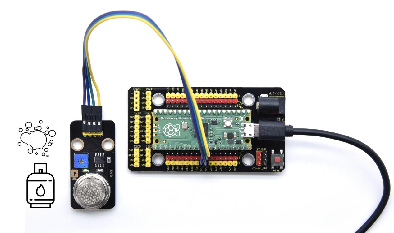
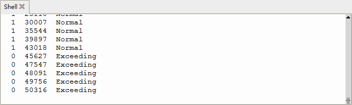
Project 26: MQ-3 Alcohol Sensor
Description
In this kit, there is a MQ-3 alcohol sensor, which uses the gas-sensing material is tin dioxide (SnO2) which has a low conductivity in clean air. When there is alcohol vapor in the environment where the sensor is located, the conductivity of the sensor increases with the increase of the alcohol gas concentration in the air. The change in conductivity can be converted into an output signal corresponding to the gas concentration using a simple circuit.
In the experiment, we read the analog value at the A0 end of the sensor and the digital value at the D0 end to judge the content of alcohol vapor in the air and whether they exceed the standard.
Working Principle
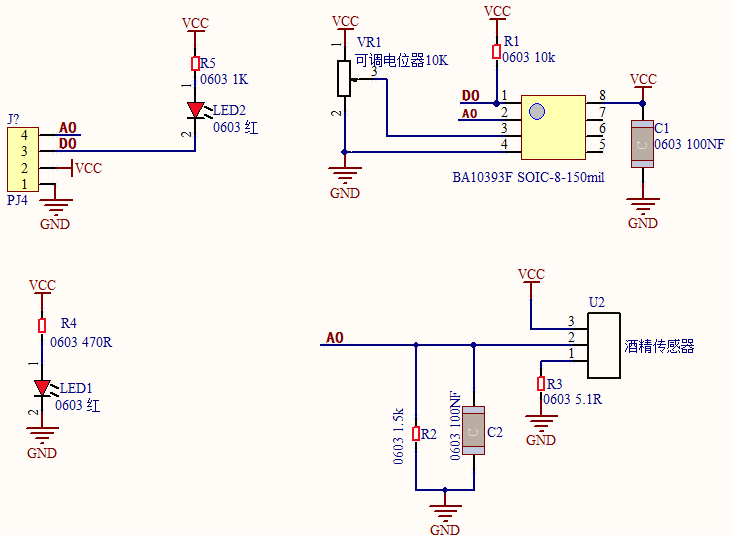
At a certain temperature, the conductivity changes with the composition of the ambient gas. When in use, A0 terminal reads the analog value corresponding to alcohol vapor; D0 terminal is connected to an LM393 chip (comparator), we can adjust and measure the alcohol vapor alarm threshold through the potentiometer, and output the digital value at D0. When the measured alcohol vapor content exceeds the critical point, the D0 terminal outputs a low level; when the measured alcohol vapor content does not exceed the critical point, the D0 terminal outputs a high level.
Components Required
|
|
|
|---|---|---|
Raspberry Pi Pico Board*1 |
Raspberry Pi Pico Expansion Board*1 |
keyestudio Alcohol Sensor*1 |
|
|
|
4P Dupont Wire*1 |
Micro USB Cable*1 |
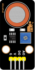
Connection Diagram
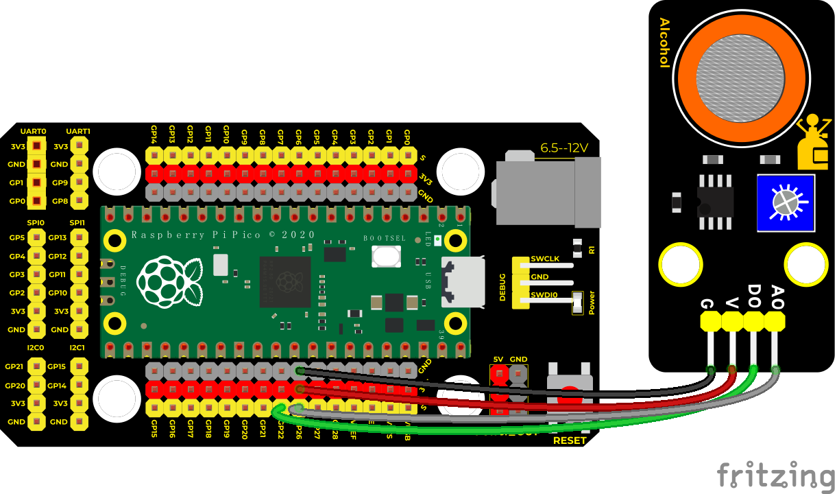
Run the test code
Find the MQ-3.py, double-click the code and click
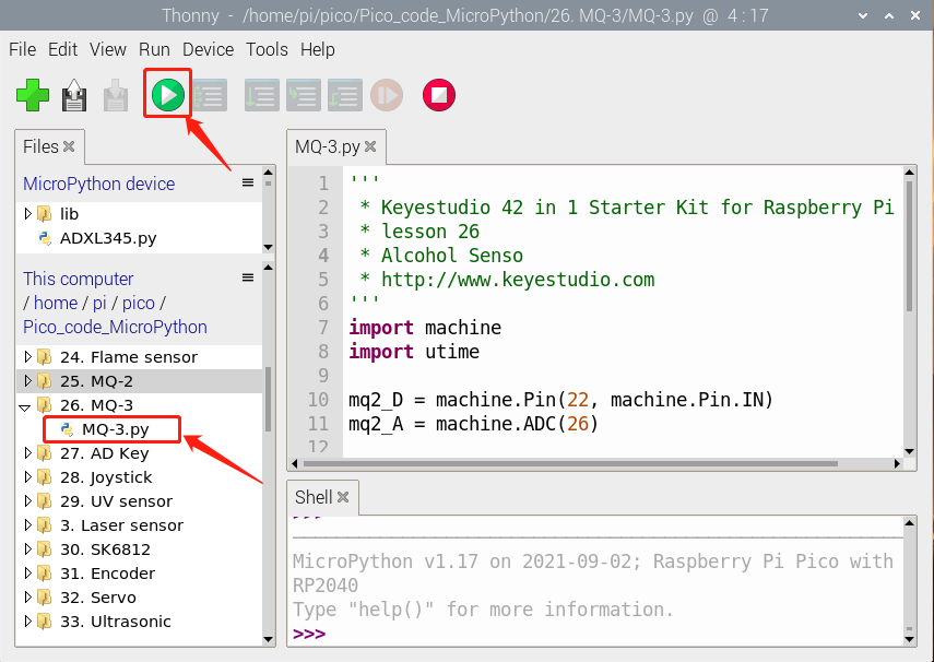
Test Code
'''
 * Keyestudio 42 in 1 Starter Kit for Raspberry Pi Pico
 * lesson 26
 * Alcohol Senso
 * http://www.keyestudio.com
'''
import machine
import utime

mq2_D = machine.Pin(22, machine.Pin.IN)
mq2_A = machine.ADC(26)

while True:
    digitalVal = mq2_D.value()
    analogVal = mq2_A.read_u16()
    print(digitalVal, end = "  ")
    print(analogVal, end = "  ")
    if digitalVal == 0:
        print("Exceeding")
    else:
        print("Normal")
    utime.sleep(0.1)
Test Result
Run the test code, the red LED on the module lights up, and the shell displays the corresponding data and characters. In the experiment, when the tested simulated value is less than or equal to 45387, the gas content does not exceed the critical point, and the yellow-green LED will be off; when the tested simulated value is greater than or equal to 45419, the gas content exceeds the critical point, and the yellow-green LED will light up; That means the critical point is in the range of 45387-45419. We can adjust the critical point by rotating the potentiometer on the sensor.
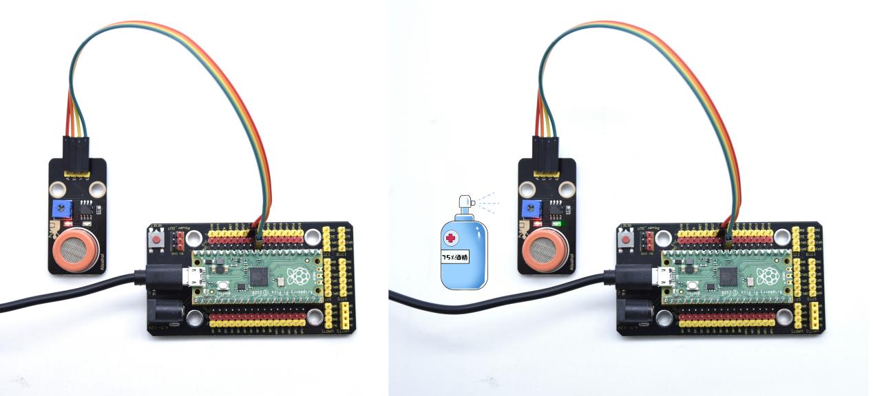
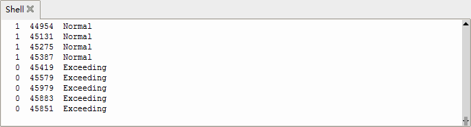
Project 27: Five-key AD Button Module

Description
When we talked about analog and digital sensors earlier, we talked about the single-channel key module. When we press the key, it outputs a low level, and when we release the key, it outputs a high level. We can only read these two digital signals. In fact, the key module ADC acquisition can also be performed. In this kit, a DIY electronic building block five-way AD button module is included.
We can judge which key is pressed through the analog value. In the experiment, we print out the key press information in the shell.
Working Principle
Let’s look at the schematic diagram, when we do not press the key, the OUT of S output to the signal end is pulled down by R1. At this time, we read the low level 0V. When we press the key SW1, the OUT of the output to the signal end S is directly connected to the VCC. At this time, we read the high level 3.3V(the figure is marked as a 10-bit ADC(0~1023) and VCC is 5V. The principle is the same. Here we have VCC of 3.3V and ADC mapped to 16 bits), which is an analog value of 65535.
Next,when we press the key SW2, the OUT terminal voltage of the signal we read is the voltage between R2 and R1, namely VCC*R1/(R2+R1), which is about 2.64V, and the analog value is about 52219.
When we press the key SW3, the OUT terminal voltage of the signal we read is the voltage between R2+R3 and R1, namely VCC*R1/(R3+R2+R1), which is about 1.99V, and the analog value is about 39360.
When we press the key SW4, the OUT terminal voltage of the signal we read is the voltage between R2+R3+R4 and R1, namely VCC*R1/(R4+R3+R2+R1), about 1.31V, and the analog value is about 26109.
Similarly, when we press the key SW5, the OUT terminal voltage of the signal we read is the voltage between R2+R3+R4+R5 and R1, namely VCC*R1/(R5+R4+R3+R2+R1), which is about 0.68V, and the analog value is about 13415.
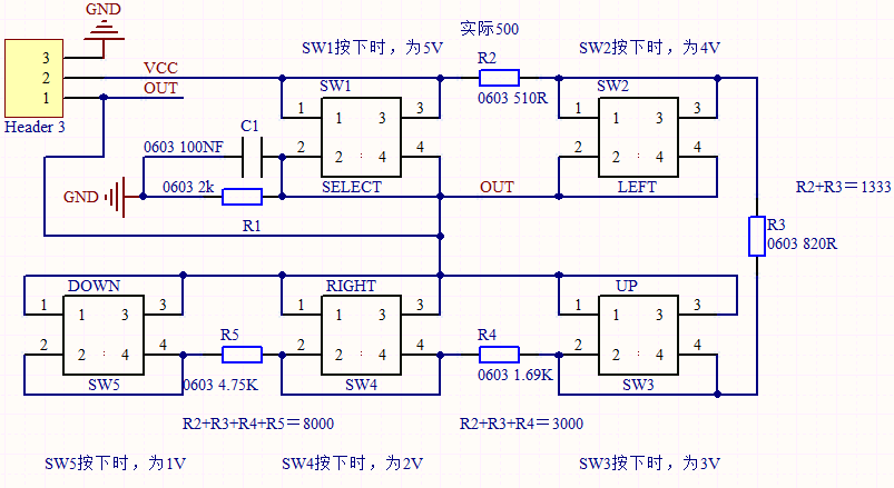
Components Required
|
|
|
|---|---|---|
Raspberry Pi Pico Board*1 |
Raspberry Pi Pico Expansion Board*1 |
keyestudio 5-Channel AD Button Module*1 |
|
|
|
3P Dupont Wire*1 |
Micro USB Cable*1 |
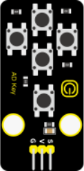
Connection Diagram
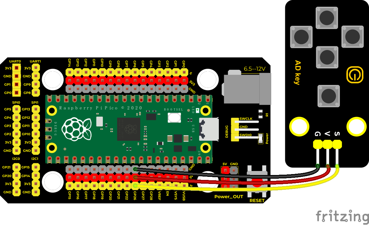
Run the test code
Find the AD key.py, double-click the code and click
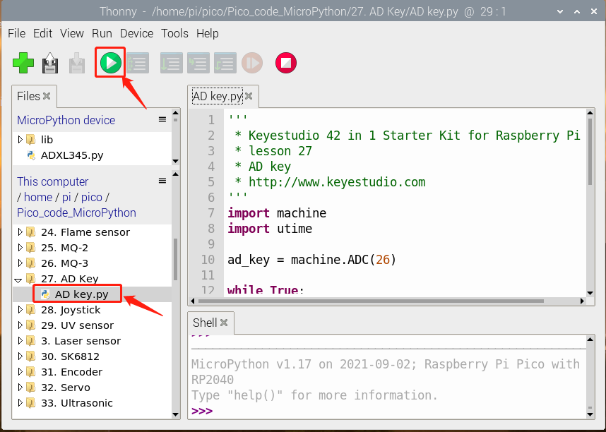
Test Code
'''
 * Keyestudio 42 in 1 Starter Kit for Raspberry Pi Pico
 * lesson 27
 * AD key
 * http://www.keyestudio.com
'''
import machine
import utime

ad_key = machine.ADC(26)

while True:
    value = ad_key.read_u16()
    print(value, end = '')
    if value <= 6000:
        print("  no key  is pressed")
    elif value <= 20000:
        print("  SW5 is pressed")
    elif value <= 32000:
        print("  SW4 is pressed")
    elif value <= 45000:
        print("  SW3 is pressed")
    elif value <= 59000:
        print("  SW2 is pressed")
    else:
        print("  SW1 is pressed")
    utime.sleep(0.1)
Code Explanation
We assign the read analog value to the variable val, and the shell displays the value of val, (our default setting is 9600, which can be changed).
We judge the read analog value. When the analog value is lower than 6000, we judge that the button is not pressed; when the analog value is between 6000 and 20000, we judge that the button SW5 is pressed; Between 20000 and 32000, we judge that the button SW4 is pressed; when the analog value is between 32000 and 45000, we judge that the button SW3 is pressed; when the analog value is between 45000 and 59000, we judge that the button SW2 is pressed. Press; otherwise, when the analog value is above 59000, we judge that the button SW1 is pressed; if we only use a fixed value, there will inevitably be errors, so we use the interval to judge.
Test Result
After uploading the test code successfully, when the button is pressed, the shell prints out the corresponding information, as shown in the figure below.
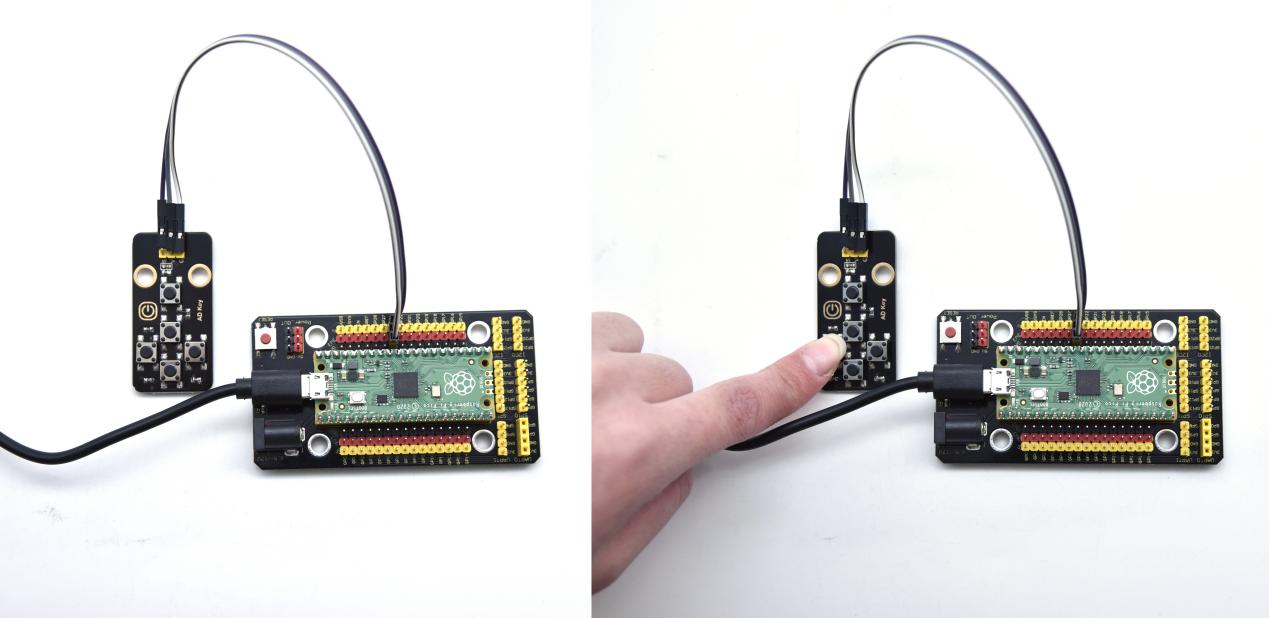
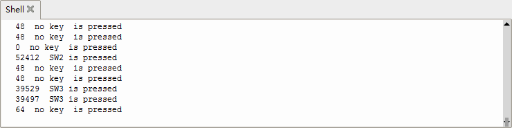
Project 28: Joystick Module

Overview
Game handle controllers are ubiquitous.
It mainly uses PS2 joysticks. When controlling it, we need to connect the X and Y ports of the module to the analog port of the single-chip microcomputer, port B to the digital port of the single-chip microcomputer, VCC to the power output port(3.3-5V), and GND to the GND of the MCU. We can read the high and low levels of two analog values and one digital port) to determine the working status of the joystick on the module.
In the experiment, two analog values(x axis and y axis) will be shown on Shell.
Working Principle
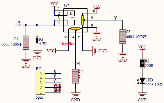
In fact, its working principle is very simple. Its inside structure is equivalent to two adjustable potentiometers and a button. When this button is not pressed and the module is pulled down by R1, low levels will be output ; on the contrary, when the button is pressed, VCC will be connected (high levels), When we move the joystick, the internal potentiometer will adjust to output different voltages, and we can read the analog value.
Components
|
|
|
|---|---|---|
Raspberry Pi Pico Board*1 |
Raspberry Pi Pico Expansion Board*1 |
Keyestudio Joystick Module*1 |
|
|
|
5P Dupont Wire*1 |
Micro USB Cable*1 |

Connection Diagram
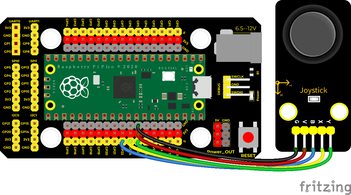
Run the Test Code
Find and double-click joystick.py, then click to run the code.
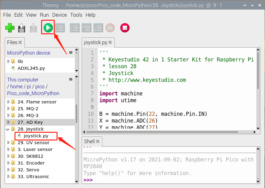
Test Code
'''
 * * Keyestudio 42 in 1 Starter Kit for Raspberry Pi Pico
 * lesson 28
 * Joystick
 * http://www.keyestudio.com
'''
import machine
import utime

B = machine.Pin(22, machine.Pin.IN)
X = machine.ADC(26)
Y = machine.ADC(27)
while True:
    B_value = B.value()
    X_value = X.read_u16()
    Y_value = Y.read_u16()
    print("button:", end = " ")
    print(B_value, end = " ")
    print("X:", end = " ")
    print(X_value, end = " ")
    print("Y:", end = " ")
    print(Y_value)
    utime.sleep(0.1)
Code Explanation
In the experiment, according to the wiring diagram, the x pin is set to ADC(26), the y pin is set to ADC(27) and the pin of the joystick is set to GP22.
Then print() function will print without changing lines.
Test Result
Run the test code and observe Shell monitor to display corresponding value. Move the joystick, analog values at X and Y axis will change then press the button, the digital value is 1, on the contrary, the value will be 0. as shown below;
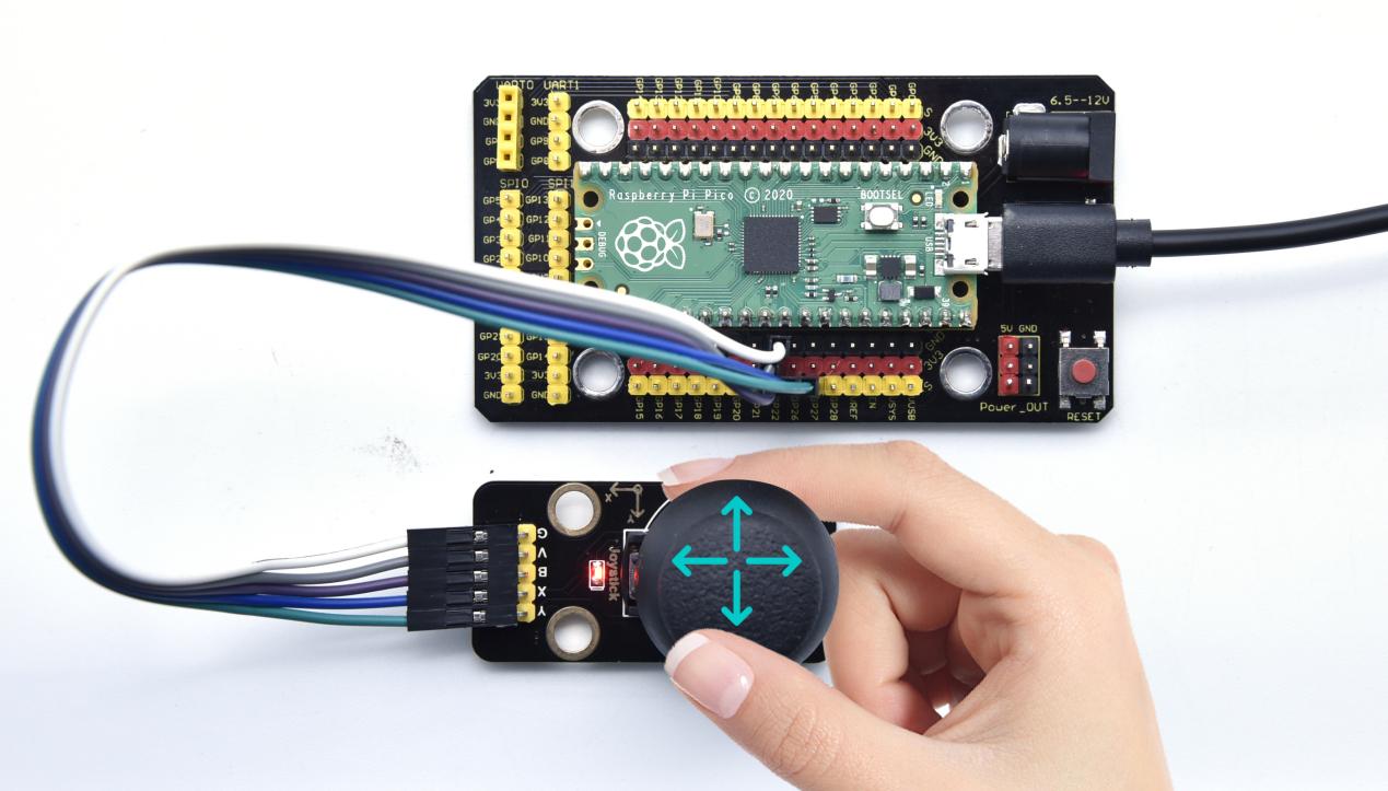
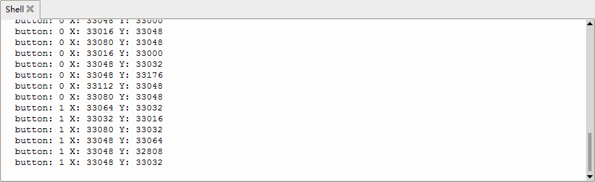
Project 29: Ultraviolet Sensor

Description
There is a ultraviolet Sensor used for UV index monitoring, UV radiation dose measurement, flame detection. Suitable for measuring UV index of smart wearable devices, such as UV index detection of watches, smart phones and outdoor equipment. It can also be used to monitor the intensity of UV light, or as a UV flame detector when UV sanitizing items. The sensor has a specific spectral response. In the experiment, we use the purple led module to test the UV module, and then display the results on the shell.
Working Principle
The output current of the UV sensor is proportional to the light intensity, and the output of the product has a very high consistency. The module circuit has been set up, and we directly use the ADC to collect the analog signal.
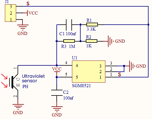
Required Components
|
|
|
|---|---|---|
Raspberry Pi Pico Board*1 |
Raspberry Pi Pico Expansion Board*1 |
Keyestudio Ultraviolet Sensor*1 |
|
|
|
3P Dupont Wire*2 |
Micro USB Cable*1 |
Keyestudio DIY Purple LED*1 |
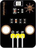
Connection Diagram
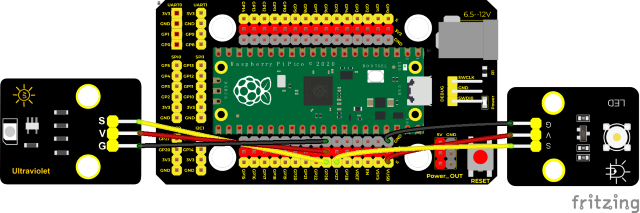
(V of led module is connected to VUSB(5V) to make the LED brighter)
Run the test code
Find and double Ultraviolet.py and click
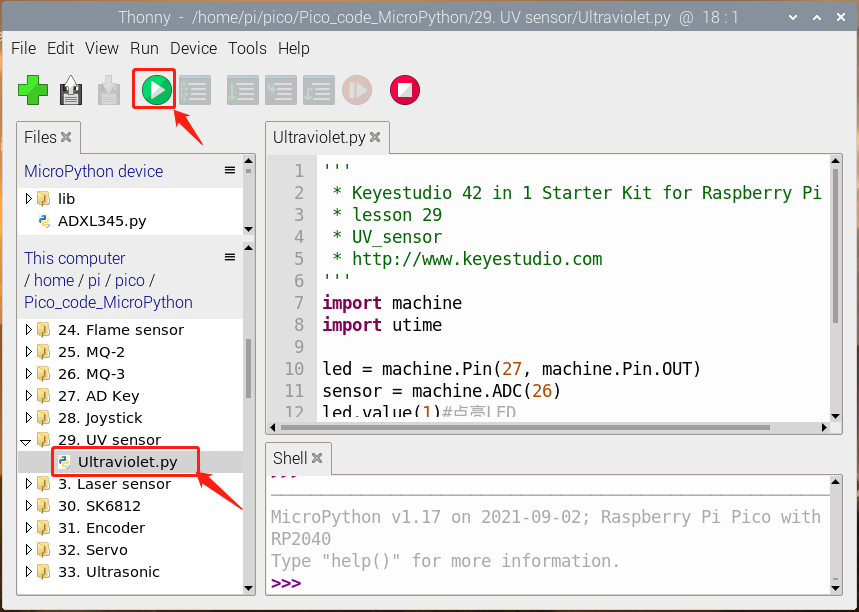
Test Code
'''
 * * Keyestudio 42 in 1 Starter Kit for Raspberry Pi Pico
 * lesson 29
 * UV_sensor
 * http://www.keyestudio.com
'''
import machine
import utime

led = machine.Pin(27, machine.Pin.OUT)
sensor = machine.ADC(26)
led.value(1)#light up LED

while True:
    analogVal = sensor.read_u16()
    print(analogVal)
    utime.sleep(0.1)
Test Result
After running the test code, the Shell displays the corresponding UV value. When we make the LED close to the ultraviolet module. Then view the data on the Shell monitor, as shown below:
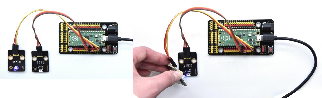
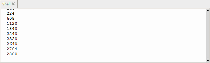
Project 30: SK6812 RGB Module

Overview
In previous lessons, we learned about the plug-in RGB module and used PWM signals to color the three pins of the module.
There is a Keyestudio 6812 RGB module whose the driving principle is different from the plug-in RGB module. It can only control with one pin. This is a set. It is an intelligent externally controlled LED light source with the control circuit and the light-emitting circuit. Each LED element is the same as a 5050 LED lamp bead, and each component is a pixel. There are four lamp beads on the module, which indicates four pixels.
In the experiment, we make different lights show different colors.
Working Principle
From the schematic diagram, we can see that these four pixel lighting beads are all connected in series. In fact, no matter how many they are, we can use a pin to control a light and let it display any color. The pixel point contains a data latch signal shaping amplifier drive circuit, a high-precision internal oscillator and a 12V high-voltage programmable constant current control part, which effectively ensures the color of the pixel point light is highly consistent.
The data protocol adopts a single-wire zero-code communication method. After the pixel is powered up and reset, the S terminal receives the data transmitted from the controller. The first 24bit data sent is extracted by the first pixel and sent to the data latch of the pixel.
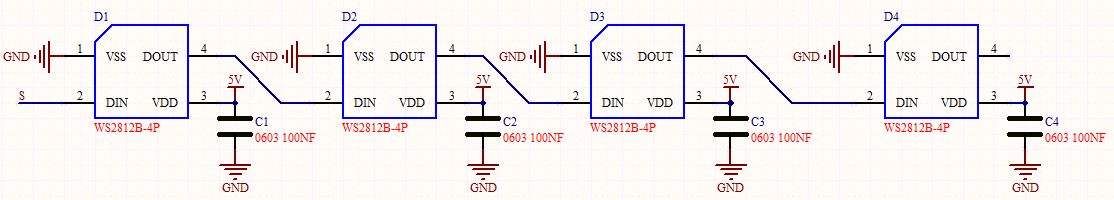
Components
|
|
|
|---|---|---|
Raspberry Pi Pico Board*1 |
Raspberry Pi Pico Expansion Board*1 |
Keyestudio 6812 RGB Module*1 |
|
|
|
3P Dupont Wire*1 |
Micro USB Cable*1 |
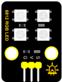
Connection Diagram

Run the test code
Find and double-click sk6812.py and click
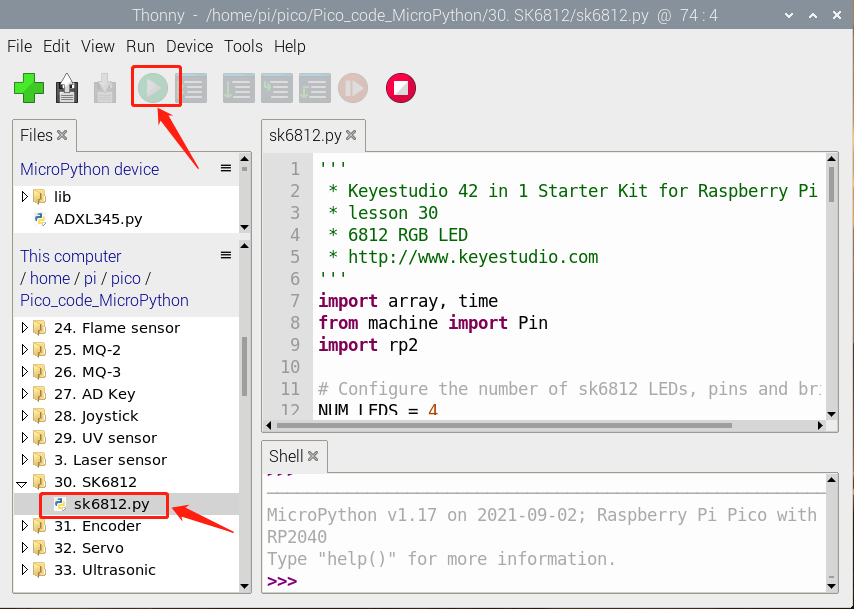
Test Code
'''
 * * Keyestudio 42 in 1 Starter Kit for Raspberry Pi Pico
 * lesson 30
 * 6812 RGB LED
 * http://www.keyestudio.com
'''
import array, time
from machine import Pin
import rp2

# Configure the number of sk6812 LEDs, pins and brightness.
NUM_LEDS = 4
PIN_NUM = 16
brightness = 0.1


@rp2.asm_pio(sideset_init=rp2.PIO.OUT_LOW, out_shiftdir=rp2.PIO.SHIFT_LEFT, autopull=True, pull_thresh=24)
def sk6812():
    T1 = 2
    T2 = 5
    T3 = 3
    wrap_target()
    label("bitloop")
    out(x, 1)               .side(0)    [T3 - 1]
    jmp(not_x, "do_zero")   .side(1)    [T1 - 1]
    jmp("bitloop")          .side(1)    [T2 - 1]
    label("do_zero")
    nop()                   .side(0)    [T2 - 1]
    wrap()


# Create the StateMachine with the sk6812 program, outputting on Pin(16).
sm = rp2.StateMachine(0, sk6812, freq=8_000_000, sideset_base=Pin(PIN_NUM))

# Start the StateMachine, it will wait for data on its FIFO.
sm.active(1)

# Display a pattern on the LEDs via an array of LED RGB values.
ar = array.array("I", [0 for _ in range(NUM_LEDS)])

def pixels_show():
    dimmer_ar = array.array("I", [0 for _ in range(NUM_LEDS)])
    for i,c in enumerate(ar):
        r = int(((c >> 8) & 0xFF) * brightness)
        g = int(((c >> 16) & 0xFF) * brightness)
        b = int((c & 0xFF) * brightness)
        dimmer_ar[i] = (g<<16) + (r<<8) + b
    sm.put(dimmer_ar, 8)
    time.sleep_ms(10)

def pixels_set(i, color):
    ar[i] = (color[1]<<16) + (color[0]<<8) + color[2]

def pixels_fill(color):
    for i in range(len(ar)):
        pixels_set(i, color)

RED = (255, 0, 0)
GREEN = (0, 255, 0)
BLUE = (0, 0, 255)
WHITE = (255, 255, 255)
BLACK = (0, 0, 0)

pixels_set(0, RED)
pixels_set(1, GREEN)
pixels_set(2, BLUE)
pixels_set(3, WHITE)
pixels_show()
time.sleep(5)
'''
for i in range(len(ar)):
    pixels_set(i, BLACK)
pixels_show()
'''
Code Explanation
A few function ports and functions:
NUM_LEDS = 4, there are four LED beads, so we set to 4.
PIN_NUM = 16, this is the pin number, we connect to GP16
brightness = 0.1, brightness setting. 1 implies brightest
pixels_show(),this function is used to refresh
pixels_set(i, color),this function is used to set locations and color of LED beads.
pixels_fill(color),display colors of LED beads
Test Result
Run the test code, wire up and power up. Then we can see four LED beads show red, green, blue and white color; as shown below.
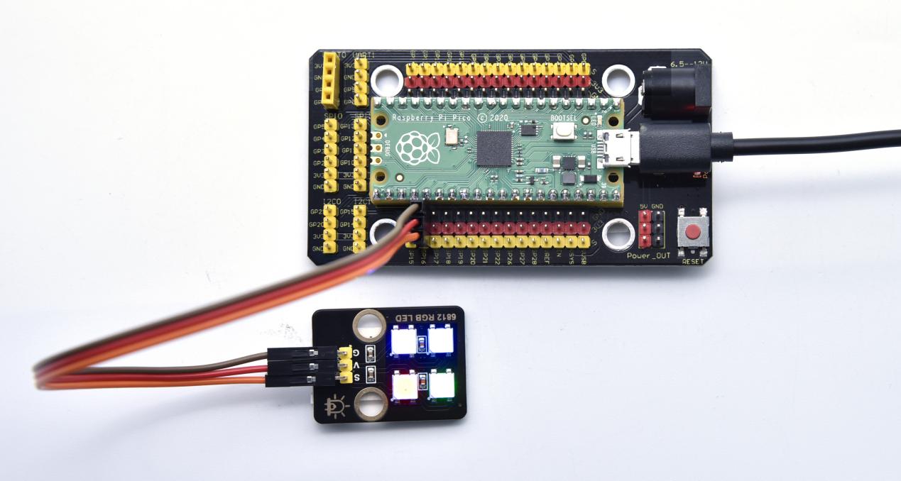
Project 31: Rotary Encoder
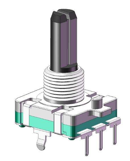
Overview
In this kit, there is a Keyestudio rotary encoder, dubbed as switch encoder. It is applied to automotive electronics, multimedia audio, instrumentation, household appliances, smart home, medical equipment and so on.
In the experiment, it it used for counting. When we rotate the rotary encoder clockwise, the set data falls by 1; if you rotate it anticlockwise, the set data is up 1; and when the middle button is pressed, the value will be show on Shell.
Working Principle
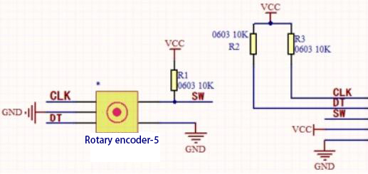
The incremental encoder converts the displacement into a periodic electric signal, and then converts this signal into a counting pulse, and the number of pulses indicates the size of the displacement.
This module mainly uses 20-pulse rotary encoder components. It can calculate the number of pulses output during clockwise and reverse rotation. There is no limit to count rotation. It resets to the initial state, that is, starts counting from 0.
Components
|
|
|
|---|---|---|
Raspberry Pi Pico Board*1 |
Raspberry Pi Pico Expansion Board*1 |
Keyestudio Rotary Encoder*1 |
|
|
|
5P Dupont Wire*1 |
Micro USB Cable*1 |
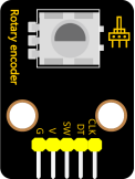
Connection Diagram
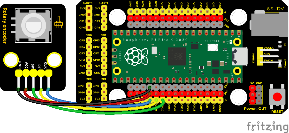
Run the test code
Find and double-click encoder.py to open it, then click to run the code.
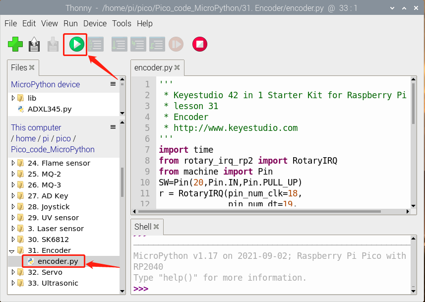
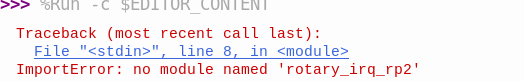
This is because we did not import the module needed by the encoder. We have mentioned how to import modules before, please refer to the previous method.
Test Code
'''
 * Keyestudio 42 in 1 Starter Kit for Raspberry Pi Pico
 * lesson 31
 * Encoder
 * http://www.keyestudio.com
'''
import time
from rotary_irq_rp2 import RotaryIRQ
from machine import Pin
SW=Pin(20,Pin.IN,Pin.PULL_UP)
r = RotaryIRQ(pin_num_clk=18,
              pin_num_dt=19,
              min_val=0,
              reverse=False,
              range_mode=RotaryIRQ.RANGE_UNBOUNDED)
val_old = r.value()
while True:
    try:
        val_new = r.value()
        if SW.value()==0 and n==0:
            print("Button Pressed")
            print("Selected Number is : ",val_new)
            n=1
            while SW.value()==0:
                continue
        n=0
        if val_old != val_new:
            val_old = val_new
            print('result =', val_new)
        time.sleep_ms(50)
    except KeyboardInterrupt:
        break
Code Explanation
In the experiment, we need to add the rotary encoder to pico, then import the module.
You only need to save the .py file to pico
After adding the rotary encoder, click File
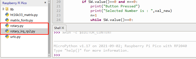
We will see the file rotary.py and rotary_irq_rp2.py. This means the we save them in the pico successfully. Then we can use from rotary_irq_rp2 import RotaryIRQ.
SW=Pin(20,Pin.IN,Pin.PULL_UP) indicates that the SW pin is connected to GP20, pin_num_clk=18 indicates that the pin CLK is connected to GP18, and pin_num_dt=19 means that the DT pin is connected to GP19. We can change these pin numbers.
try/except is the python language exception capture processing statement, try executes the code, except executes the code when an exception occurs, and when we press Ctrl+C, the program exits.
r.value() returns the value of the encoder.
Test Result
Run the test code, observe the Shell below. Rotate the encoder clockwise, the displayed data decrease; rotate the encoder counterclockwise, the displayed data increase; press the button of the encoder, the displayed data is the value of the encoder, as shown in the figure below.
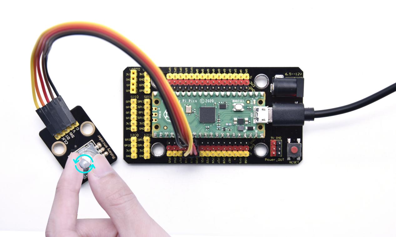
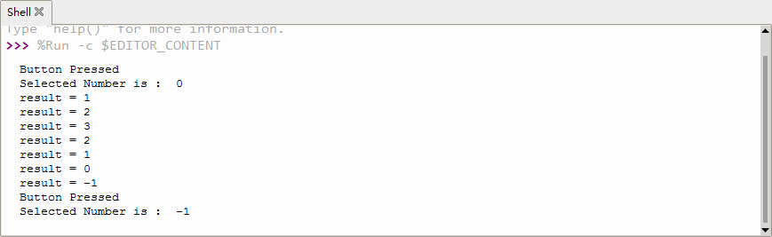
Project 32: Servo Control

Overview
Servo motor is a position control rotary actuator. It mainly consists of a housing, a circuit board, a core-less motor, a gear and a position sensor. Its working principle is that the servo receives the signal sent by MCU or receiver and produces a reference signal with a period of 20ms and width of 1.5ms, then compares the acquired DC bias voltage to the voltage of the potentiometer and obtain the voltage difference output.
In general, servo has three lines in brown, red and orange. The brown wire is grounded, the red one is a positive pole line and the orange one is a signal line.
Working Principle

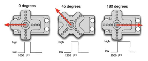
When the motor speed is constant, the potentiometer is driven to rotate through the cascade reduction gear, which leads that the voltage difference is 0, and the motor stops rotating. Generally, the angle range of servo rotation is 0° –180 °.
The rotation angle of servo motor is controlled by regulating the duty cycle of PWM (Pulse-Width Modulation) signal. The standard cycle of PWM signal is 20ms (50Hz). Theoretically, the width is distributed between 1ms-2ms, but in fact, it’s between 0.5ms-2.5ms. The width corresponds the rotation angle from 0° to 180°. But note that for different brand motors, the same signal may have different rotation angles.

Components
|
|
|
|
|---|---|---|---|
Raspberry Pi Pico Board*1 |
Raspberry Pi Pico Expansion Board*1 |
Servo*1 |
Micro USB Cable*1 |
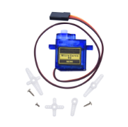
Connection Diagram
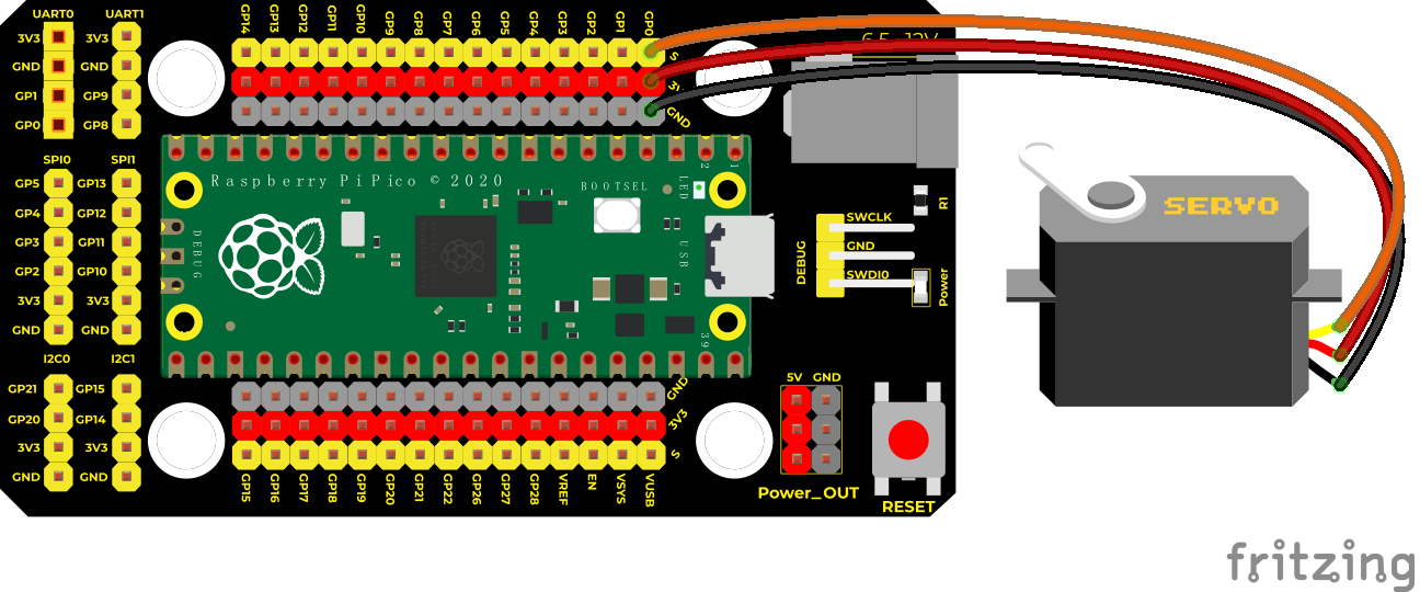
Run the Test Code
Find Servo test 1.py and Servo test 2.py, double-click to open them. Then click to run the code.
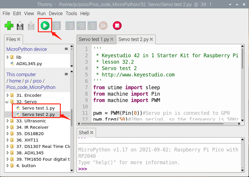
Code 1:
'''
 * Keyestudio 42 in 1 Starter Kit for Raspberry Pi Pico
 * lesson 32.1
 * Servo test 1
 * http://www.keyestudio.com
'''
from machine import Pin, PWM
import time
pwm = PWM(Pin(0))
pwm.freq(50)

'''
0°----2.5%----1638
45°----5%----3276
90°----7.5%----4915
135°----10%----6553
180°----12.5%----8192
'''
angle_0 = 1638
angle_90 = 4915
angle_180 = 8192

while True:
    pwm.duty_u16(angle_0)
    time.sleep(1)
    pwm.duty_u16(angle_90)
    time.sleep(1)
    pwm.duty_u16(angle_180)
    time.sleep(1)
Code 2:
'''
 * Keyestudio 42 in 1 Starter Kit for Raspberry Pi Pico
 * lesson 32.2
 * Servo test 2
 * http://www.keyestudio.com
'''
from utime import sleep
from machine import Pin
from machine import PWM

pwm = PWM(Pin(0))#the pin of the servo is connected with GPO
pwm.freq(50)#20ms,frequency is 50Hz
'''
Duty cycles that angles correspond
0°----2.5%----1638
45°----5%----3276
90°----7.5%----4915
135°----10%----6553
180°----12.5%----8192
Considering the error, set the duty cycle at 1000~9000, so that it can rotate 0~180 degrees smoothly
'''
# set rotation angles of the servo
def setServoCycle (position):
    pwm.duty_u16(position)
    sleep(0.01)

# calculate rotation angles into duty cycle
def convert(x, i_m, i_M, o_m, o_M):
    return max(min(o_M, (x - i_m) * (o_M - o_m) // (i_M - i_m) + o_m), o_m)

while True:
    for degree in range(0, 180, 1):#rotate from 0° to 180°
        pos = convert(degree, 0, 180, 1000, 9000)
        setServoCycle(pos)

    for degree in range(180, 0, -1):#rotate from 180° to 0°
        pos = convert(degree, 0, 180, 1000, 9000)
        setServoCycle(pos)
Code Explanation
Code 1:
According to the angle of the signal pulse width, it is converted into a duty cycle. The formula is: 2.5+angle/180*10. The PWM pin resolution of Pi Pico is 2^16 = 65535. When converted to 0 degree, its duty cycle is 65535 * 2.5% = 1638.375 , when the angle is 180 degrees, its duty cycle value is 65535 * 12.5% = 8191.875, these two values will be related to the program, considering the error and rotation angle, I set the duty cycle at 1000 Between 9000 and 9000, the servo can rotate smoothly 0~180 degrees.
Code 2:
convert(x, i_m, i_M, o_m, o_M): x is the value we want to map; i_m, i_M are the lower and upper limits of the current value; o_m, o_M are the lower and upper limits of the target range we want to map to.
Test Result
Result 1:
Run the test code successfully, the servo rotates cyclically from 0 degrees, 90 degrees, and 180 degrees.
Test Result 2:
Run the test code successfully, the servo rotates back and forth from 0 to 180 degrees, one degree every 10ms.
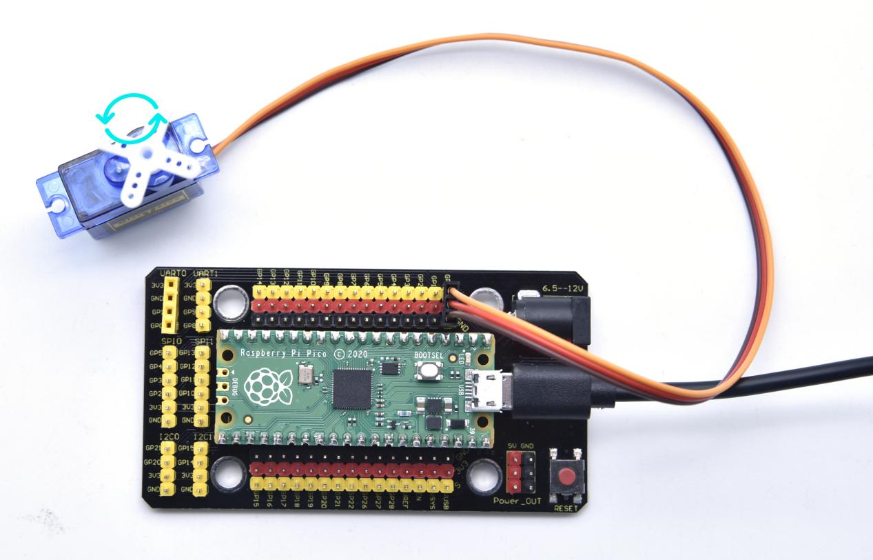
Project 33: Ultrasonic Sensor
Overview
In this kit, there is a keyes HC-SR04 ultrasonic sensor, which can detect obstacles in front and the detailed distance between the sensor and the obstacle. Its principle is the same as that of bat flying. It can emit the ultrasonic signals that cannot be heard by humans. When these signals hit an obstacle and come back immediately. The distance between the sensor and the obstacle can be calculated by the time gap of emitting signals and receiving signals.
In the experiment, we use the sensor to detect the distance between the sensor and the obstacle, and print the test result.
Ultrasonic detector module can provide 2cm-450cm non-contact sensing distance, and its ranging accuracy is up to 3mm, very good to meet the normal requirements. The module includes an ultrasonic transmitter and receiver as well as the corresponding control circuit.
Working Principle
The most common ultrasonic ranging method is the echo detection. As shown below; when the ultrasonic emitter emits the ultrasonic waves towards certain direction, the counter will count. The ultrasonic waves travel and reflect back once encountering the obstacle. Then the counter will stop counting when the receiver receives the ultrasonic waves coming back.
The ultrasonic wave is also sound wave, and its speed of sound V is related to temperature. Generally, it travels 340m/s in the air. According to time t, we can calculate the distance s from the emitting spot to the obstacle. $$ s=340t/2 $$ The HC-SR04 ultrasonic ranging module can provide a non-contact distance sensing function of 2cm-400cm, and the ranging accuracy can reach as high as 3mm; the module includes an ultrasonic transmitter, receiver and control circuit. Basic working principle:
1. First pull down the TRIG, and then trigger it with at least 10us high level signal;
2. After triggering, the module will automatically transmit eight 40KHZ square waves, and automatically detect whether there is a signal to return.
3. If there is a signal returned back, through the ECHO to output a high level, the duration time of high level is actually the time from emission to reception of ultrasonic.
$$
Test Distance = High Level Duration * 340m/s * 0.5
$$
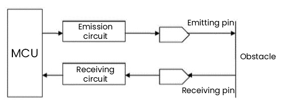
Components
|
|
|
|---|---|---|
Raspberry Pi Pico Board*1 |
Raspberry Pi Pico Expansion Board*1 |
keyestudio SR01 Ultrasonic Sensor*1 |
|
|
|
4P Dupont Wire*1 |
Micro USB Cable*1 |
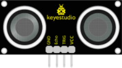
Connection Diagram
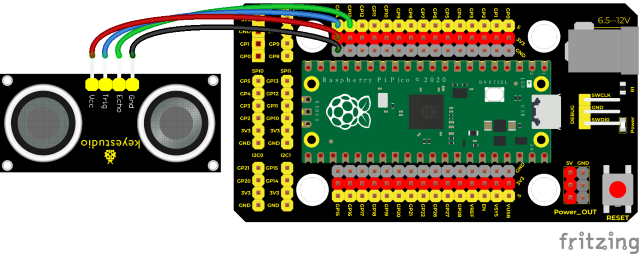
Run the test code
Find and double-click ultrasonic.pyto to open it, then click to run the code.
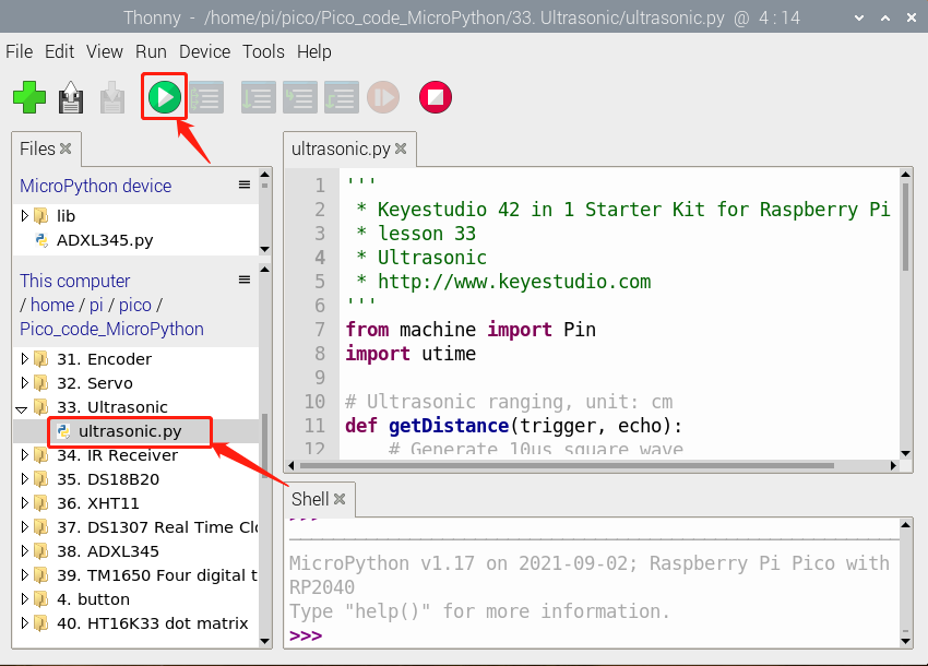
Test Code
'''
 * Keyestudio 42 in 1 Starter Kit for Raspberry Pi Pico
 * lesson 33
 * Ultrasonic
 * http://www.keyestudio.com
'''
from machine import Pin
import utime

# ultrasonic ranging,unit:cm
def getDistance(trigger, echo):
    # produce 10us square waves
    trigger.low()   #preserve a short low level to secure a high level:
    utime.sleep_us(2)
    trigger.high()
    utime.sleep_us(10)#pull up levels, wait for 10ms and set to low levels
    trigger.low()

    while echo.value() == 0: #build up a while loop pin 0 and record time
        start = utime.ticks_us()
    while echo.value() == 1: #build up a while loop pin 1 and record time
        end = utime.ticks_us()
    d = (end - start) * 0.0343 / 2 #travel time x sound speed(343.2 m/s,0.0343cm for one ms),the distance is divided by 2
    return d

# set pins
trigger = Pin(14, Pin.OUT)
echo = Pin(13, Pin.IN)
# main program
while True:
    distance = getDistance(trigger, echo)
    print("The distance is :{:.2f} cm".format(distance))
    utime.sleep(0.1)
Code Explanation
The maximum distance of the sensor is 3-4m,the minimum distance is 2cm. The distance value on the Shell is the distance between the sensor and the obstacle
utime.ticks_us(): return the program to run
Test Result
Run the test code and observe the Shell monitor.
Display the distance between the sensor and the obstacle, the unit is cm, as shown below.
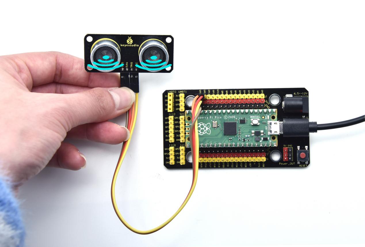
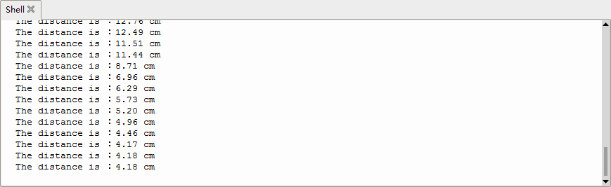
Project 34: IR Receiver Module

Overview
There is no doubt that infrared remote control is ubiquitous in daily life. It is used to control various household appliances, such as TVs, stereos, video recorders and satellite signal receivers. Infrared remote control is composed of infrared transmitting and infrared receiving systems, that is, an infrared remote control and infrared receiving module and a single-chip microcomputer capable of decoding.
In this experiment, we need to know how to use the infrared receiving sensor. The infrared receiving sensor mainly uses the VS1838B infrared receiving sensor element. It integrates receiving, amplifying, and demodulating. The internal IC has already completed the demodulation, and the output is a digital signal. It can receive 38KHz modulated remote control signal. In the experiment, we use the IR receiver to receive the infrared signal emitted by the external infrared transmitting device, and display the received signal in the shell.
Working Principle
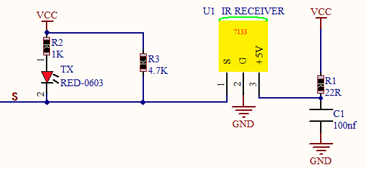
The main part of the IR remote control system is modulation, transmission and reception. The modulated carrier frequency is generally between 30khz and 60khz, and most of them use a square wave of 38kHz and a duty ratio of 1/3. A 4.7K pull-up resistor R3 is added to the signal end of the infrared receiver.
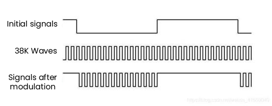
Components
|
|
|
|---|---|---|
Raspberry Pi Pico Board*1 |
Raspberry Pi Pico Expansion Board*1 |
Keyestudio DIY IR Receiver*1 |
|
|
|
3P Dupont Wire*1 |
Micro USB Cable*1 |
Remote Control*1 |
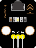

Connection Diagram
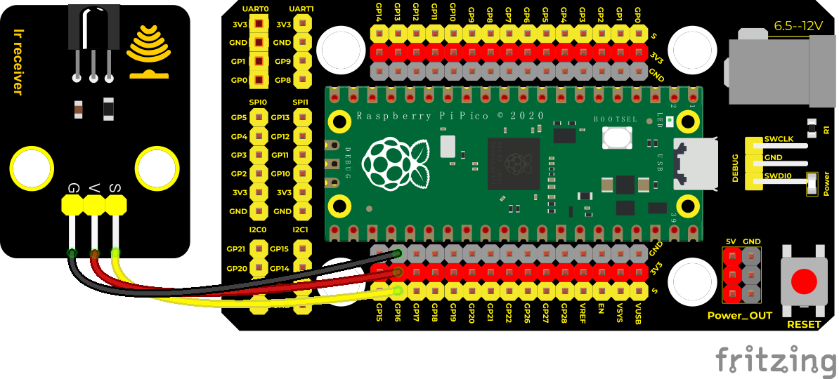
Run the test code
Double-click IR receive.py,and click to run the code.
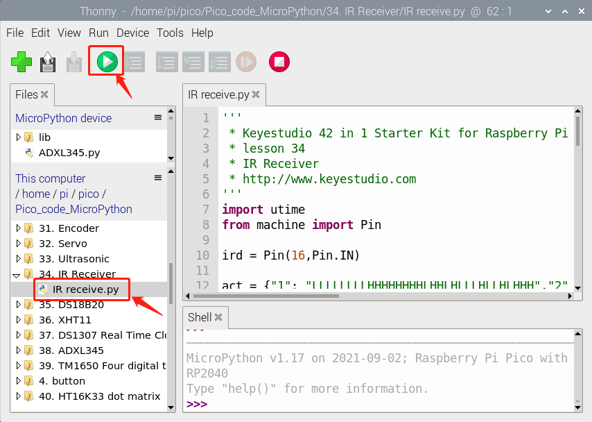
Test Code
'''
 * Keyestudio 42 in 1 Starter Kit for Raspberry Pi Pico
 * lesson 34
 * IR Receiver
 * http://www.keyestudio.com
'''
import utime
from machine import Pin

ird = Pin(16,Pin.IN)

act = {"1": "LLLLLLLLHHHHHHHHLHHLHLLLHLLHLHHH","2": "LLLLLLLLHHHHHHHHHLLHHLLLLHHLLHHH","3": "LLLLLLLLHHHHHHHHHLHHLLLLLHLLHHHH",
       "4": "LLLLLLLLHHHHHHHHLLHHLLLLHHLLHHHH","5": "LLLLLLLLHHHHHHHHLLLHHLLLHHHLLHHH","6": "LLLLLLLLHHHHHHHHLHHHHLHLHLLLLHLH",
       "7": "LLLLLLLLHHHHHHHHLLLHLLLLHHHLHHHH","8": "LLLLLLLLHHHHHHHHLLHHHLLLHHLLLHHH","9": "LLLLLLLLHHHHHHHHLHLHHLHLHLHLLHLH",
       "0": "LLLLLLLLHHHHHHHHLHLLHLHLHLHHLHLH","Up": "LLLLLLLLHHHHHHHHLHHLLLHLHLLHHHLH","Down": "LLLLLLLLHHHHHHHHHLHLHLLLLHLHLHHH",
       "Left": "LLLLLLLLHHHHHHHHLLHLLLHLHHLHHHLH","Right": "LLLLLLLLHHHHHHHHHHLLLLHLLLHHHHLH","Ok": "LLLLLLLLHHHHHHHHLLLLLLHLHHHHHHLH",
       "*": "LLLLLLLLHHHHHHHHLHLLLLHLHLHHHHLH","#": "LLLLLLLLHHHHHHHHLHLHLLHLHLHLHHLH"}

def read_ircode(ird):
    wait = 1
    complete = 0
    seq0 = []
    seq1 = []

    while wait == 1:
        if ird.value() == 0:
            wait = 0
    while wait == 0 and complete == 0:
        start = utime.ticks_us()
        while ird.value() == 0:
            ms1 = utime.ticks_us()
        diff = utime.ticks_diff(ms1,start)
        seq0.append(diff)
        while ird.value() == 1 and complete == 0:
            ms2 = utime.ticks_us()
            diff = utime.ticks_diff(ms2,ms1)
            if diff > 10000:
                complete = 1
        seq1.append(diff)

    code = ""
    for val in seq1:
        if val < 2000:
            if val < 700:
                code += "L"
            else:
                code += "H"
    # print(code)
    command = ""
    for k,v in act.items():
        if code == v:
            command = k
    if command == "":
        command = code
    return command

while True:
    command = read_ircode(ird)
    print(command)
    utime.sleep(0.5)
Test Result
Find the infrared remote control, pull out the insulating sheet, and press the button at the receiving head of the infrared receiving sensor. After receiving the signal, the LED on the infrared receiving sensor also starts to flash, as shown in the figure below.
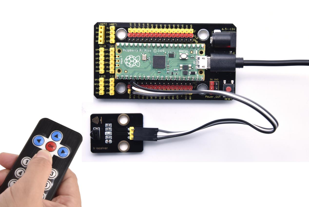
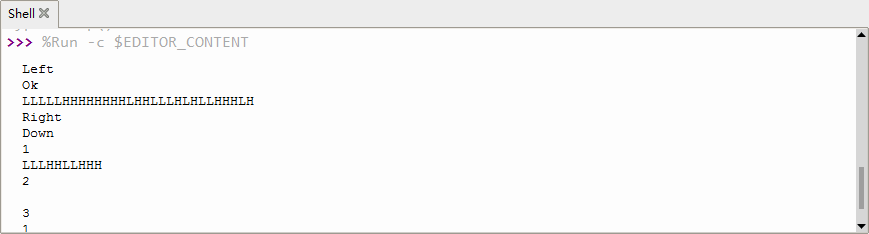
Project 35: DS18B20 Temperature Sensor

Description
The DS18B20 is a 1-wire programmable Temperature sensor from maxim integrated. It is widely used to measure temperature in hard environments like in chemical solutions, mines or soil etc. The constriction of the sensor is rugged and also can be purchased with a waterproof option making the mounting process easy. It can measure a wide range of temperature from -55°C to +125° with a decent accuracy of ±5°C. Each sensor has a unique address and requires only one pin of the MCU to transfer data so it a very good choice for measuring temperature at multiple points without compromising much of your digital pins on the microcontroller.
Working Principle
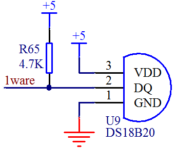
The hardware interface of the 1-Wire bus is very simple, just connect the data pin of the DS18B20 to an IO port of the microcontroller. The timing of the 1-Wire bus is relatively complex. Many students can’t understand the timing diagram independently here. We have encapsulated the complex timing operations in the library, and you can use the library functions directly.
Schematic Diagram of DS18B20
This can save up to 12-bit temperature vale. In the register, save in code complement. As shown below;
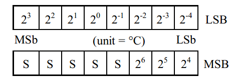
A total of 2 bytes, LSB is the low byte, MSB is the high byte, where MSb is the high byte of the byte, LSb is the low byte of the byte. As you can see, the binary number, the meaning of the temperature represented by each bit, is expressed. Among them, S represents the sign bit, and the lower 11 bits are all powers of 2, which are used to represent the final temperature. The temperature measurement range of DS18B20 is from -55 degrees to +125 degrees, and the expression form of temperature data, S represents positive and negative temperature, and the resolution is 2﹣⒋, which is 0.0625.
Required Components
|
|
|
|---|---|---|
Raspberry Pi Pico Board*1 |
Raspberry Pi Pico Expansion Board*1 |
Keyestudio DIY 18B20 Temperature Sensor*1 |
|
|
|
3P Dupont Wire*1 |
Micro USB Cable*1 |
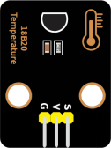
Connection Diagram
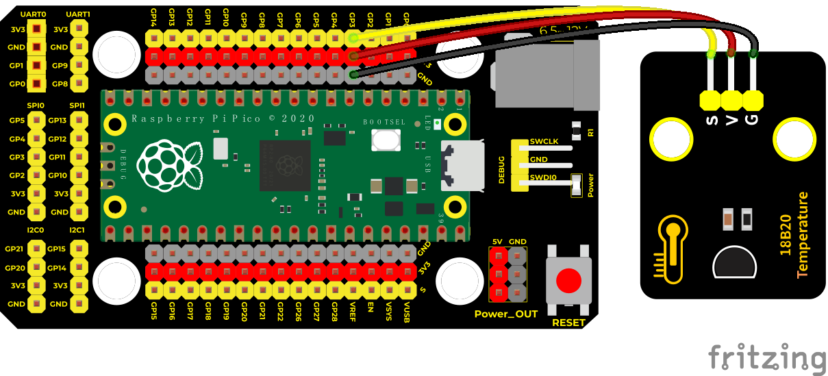
Import the 18B20 module,save the test code in the pico and name onewire.py
Test Code
'''
 * Keyestudio 42 in 1 Starter Kit for Raspberry Pi Pico
 * lesson 35
 * DS18B20
 * http://www.keyestudio.com
'''
import machine, onewire, ds18x20, time
ds_pin = machine.Pin(3)
ds_sensor = ds18x20.DS18X20(onewire.OneWire(ds_pin))
roms = ds_sensor.scan()
print('Found DS devices: ', roms)

while True:
  ds_sensor.convert_temp()
  time.sleep_ms(750)
  for rom in roms:
    #print(rom)
    print(ds_sensor.read_temp(rom))
  time.sleep(1)
Code Explanation
We need to import the DS18B20 module.
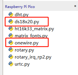
Set the pin to 3.
time.sleep_ms(750) It means that it will take at least 750ms to complete the conversion.
Shell means temperature value, ds_sensor.read_temp(rom) is used to read temperature value.
Test Result
Run the test code, the shell displays the temperature of the current environment, as shown below.
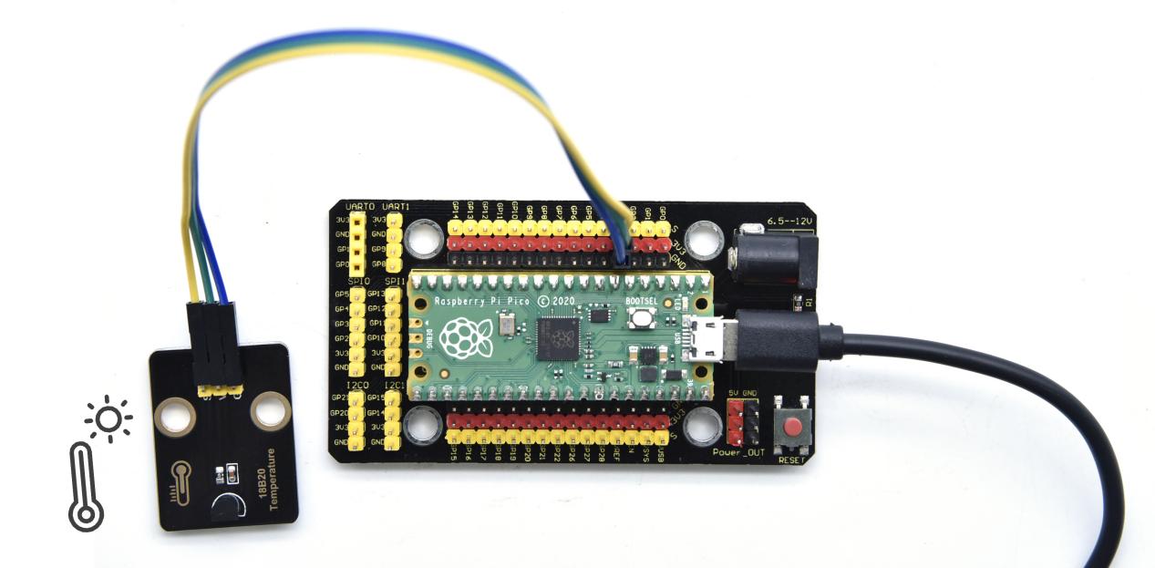
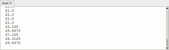
Project 36: XHT11 Temperature and Humidity Sensor
Description
This DHT11 temperature and humidity sensor is a composite sensor which contains a calibrated digital signal output of the temperature and humidity.
DHT11 temperature and humidity sensor uses the acquisition technology of the digital module and temperature and humidity sensing technology, ensuring high reliability and excellent long-term stability.
It includes a resistive element and a NTC temperature measuring device.
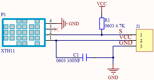
Working Principle
The communication and synchronization between the single-chip microcomputer and XHT11 adopts the single bus data format. The communication time is about 4ms. The data is divided into fractional part and integer part.
Operation process: A complete data transmission is 40bit, high bit first out. Data format: 8bit humidity integer data + 8bit humidity decimal data + 8bit temperature integer data + 8bit temperature decimal data + 8bit checksum
8-bit checksum: 8-bit humidity integer data + 8-bit humidity decimal data + 8-bit temperature integer data + 8-bit temperature decimal data “Add the last 8 bits of the result.
Required Components
|
|
|
|---|---|---|
Raspberry Pi Pico Board*1 |
Raspberry Pi Pico Expansion Board*1 |
Keyestudio XHT11 Temperature and Humidity Sensor(compatible with DHT11)*1 |
|
|
|
3P Dupont Wire*1 |
Micro USB Cable*1 |
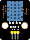
Connection Diagram
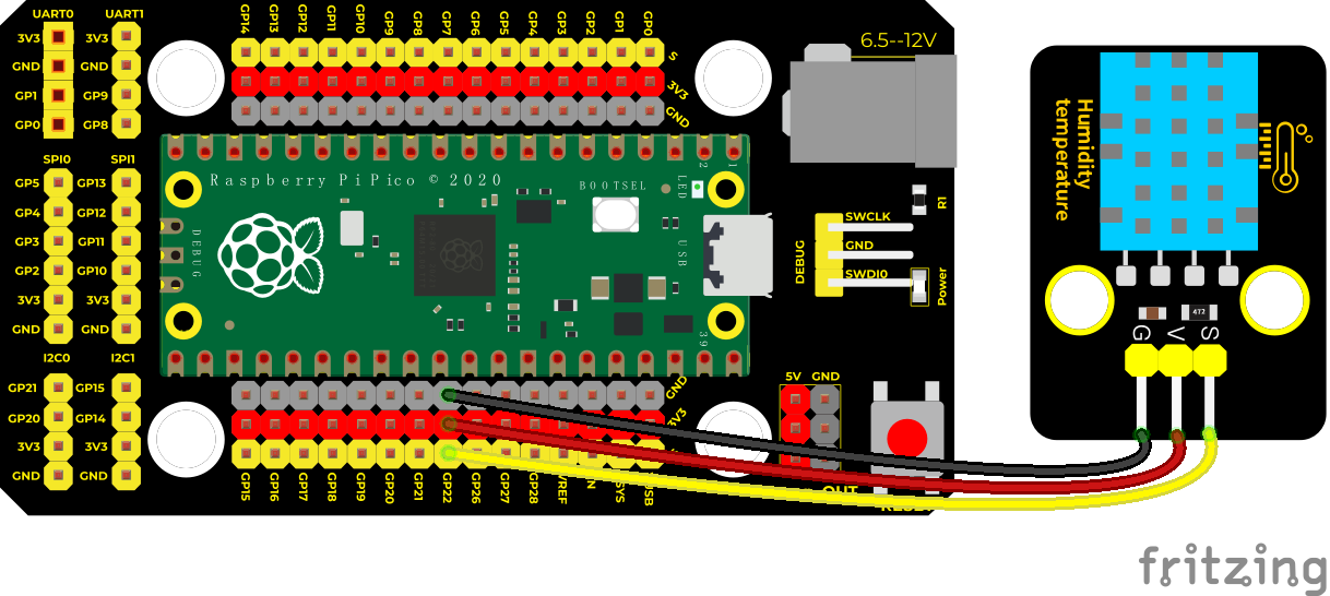
Run the test code
Import the xht11 module, save it in pico and name dht.py
Test Code
'''
 * Keyestudio 42 in 1 Starter Kit for Raspberry Pi Pico
 * lesson 36
 * xht11
 * http://www.keyestudio.com
'''
import machine
import utime
import dht

pin = machine.Pin(22, machine.Pin.OUT, machine.Pin.PULL_DOWN)
sensor = dht.DHT11(pin)

while True:
    print("temperature:{} ℃  humidity:{} %".format(sensor.temperature, sensor.humidity))
    utime.sleep(1)
Code Explanation
1. In the experiment, we need to import the XHT11 library:
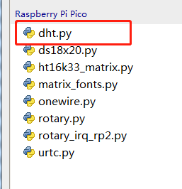
2. We set the pin to GP22, read the temperature data sensor.temperature, read the humidity data sensor.humidity.
Test Result
After running the test code, the shell displays the temperature and humidity data, as shown below.
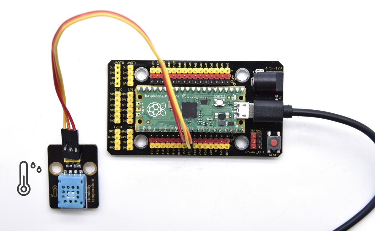
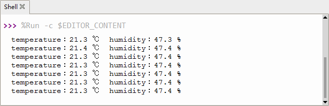
Project 37: DS1307 Clock Module

Overview
The DS1307 serial real-time clock (RTC) is a low-power, full binary-coded decimal (BCD) clock/calendar plus 56 bytes of NV SRAM. Address and data are transferred serially through an I2C, bidirectional bus.
The clock/calendar provides seconds, minutes, hours, day, date, month, and year information. The end of the month date is automatically adjusted for months with fewer than 31 days, including corrections for leap year. The clock operates in either the 24-hour or 12-hour format with AM/PM indicator. The DS1307 has a built-in power-sense circuit that detects power failures and automatically switches to the backup supply.
Timekeeping operation continues while the part operates from the backup supply.
Working Principle
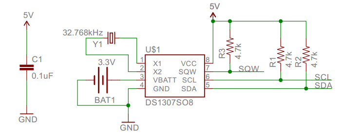
Detailed address and data:
Serial real-time clock records year, month, day, hour, minute, second and week; AM and PM indicate morning and afternoon respectively; 56 bytes of NVRAM store data; 2-wire serial port; programmable square wave output; power failure detection and automatic switching circuit; battery current is less than 500nA.
Pins description:X1, 32.768kHz crystal terminal ;
VBAT:X2:+3V input;
SDA:serial data;
SCL:serial clock;
SQW/OUT:square waves/output drivers
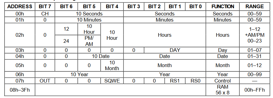
Components
|
|
|
|---|---|---|
Raspberry Pi Pico Board*1 |
Raspberry Pi Pico Expansion Board*1 |
Keyestudio DS1307 Clock Module*1 |
|
|
|
4P Dupont Wire*1 |
Micro USB Cable*1 |
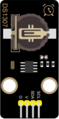
Connection Diagram
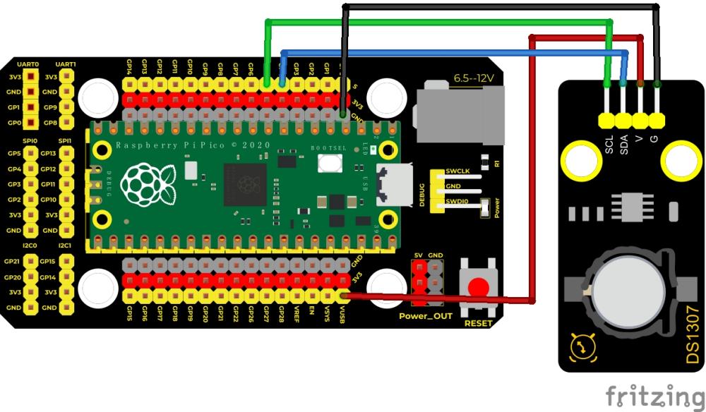
VUSB is 5V,then connect the power to VUSB.
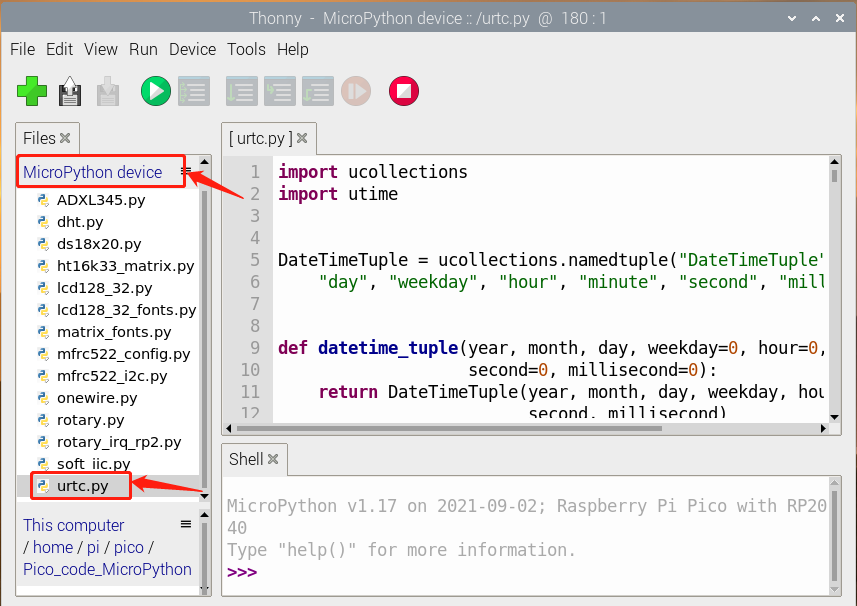
Run the DS1307.py:
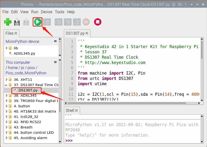
Test Code
'''
 * Keyestudio 42 in 1 Starter Kit for Raspberry Pi Pico
 * lesson 37
 * DS1307 Real Time Clock
 * http://www.keyestudio.com
'''
from machine import I2C, Pin
from urtc import DS1307
import utime

i2c = I2C(1,scl = Pin(15),sda = Pin(14),freq = 400000)
rtc = DS1307(i2c)

year = int(input("Year : "))
month = int(input("month (Jan --> 1 , Dec --> 12): "))
date = int(input("date : "))
day = int(input("day (1 --> monday , 2 --> Tuesday ... 0 --> Sunday): "))
hour = int(input("hour (24 Hour format): "))
minute = int(input("minute : "))
second = int(input("second : "))

now = (year,month,date,day,hour,minute,second,0)
rtc.datetime(now)

#(year,month,date,day,hour,minute,second,p1) = rtc.datetime()
while True:
    DateTimeTuple = rtc.datetime()
    print(DateTimeTuple[0], end = '-')
    print(DateTimeTuple[1], end = '-')
    print(DateTimeTuple[2], end = '  ')
    print(DateTimeTuple[4], end = ':')
    print(DateTimeTuple[5], end = ':')
    print(DateTimeTuple[6], end = '  week:')
    print(DateTimeTuple[3])
    utime.sleep(1)
Code Explanation
**rtc.datetime():**Return a tuple of time. When the program is running, we set the “please input” program, run the code, it will prompt us to input the time and date, after the input is completed, the data will be printed every second.
DateTimeTuple[0]: save time
DateTimeTuple[1]: save months
DateTimeTuple[2]: save days
DateTimeTuple[3]: save weeks
Rtc.GetDateTime().Month(): return months
DateTimeTuple[4]: save hours
DateTimeTuple[5]: save minutes
DateTimeTuple[6]: save seconds
Test Result
Upload the code and view the Shell monitor. We can see the displayed year, month, day, hour, minute, second and week, as shown below;
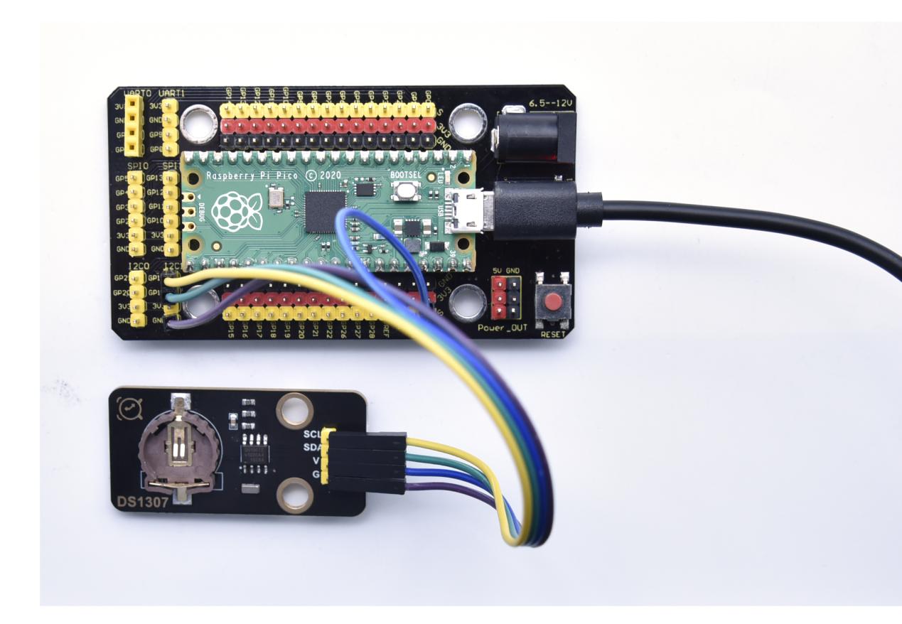
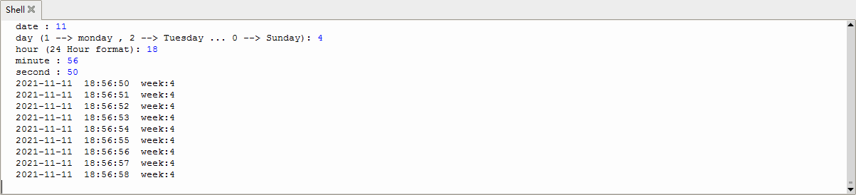
Project 38: ADXL345 Acceleration Sensor
Description
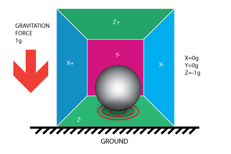
In this kit, there is a DIY electronic building block ADXL345 acceleration sensor module, which uses the ADXL345BCCZ chip. The chip is a small, thin, low-power 3-axis accelerometer with a high resolution (13 bits) and a measurement range of ±16g that can measure both dynamic acceleration due to motion or impact as well as stationary acceleration such as gravitational acceleration, making the device usable as a tilt sensor.
In the study, we test the acceleration value of sensor X, Y and Z axis. What’s more, we show the test data in the shell.
Working Principle

The ADXL345 is a complete 3-axis acceleration measurement system with a selection of measurement ranges of ±2 g, ±4 g, ±8 g or ±16 g. Its digital output data is in 16-bit binary complement format and can be accessed through an SPI (3-wire or 4-wire) or I2C digital interface.
The sensor can measure static acceleration due to gravity in tilt detection applications, as well as dynamic acceleration due to motion or impact. Its high resolution (3.9mg/LSB) enables measurement of tilt Angle changes of less than 1.0°.
Required Components
|
|
|
|---|---|---|
Raspberry Pi Pico Board*1 |
Raspberry Pi Pico Expansion Board*1 |
Keyestudio ADXL345 Acceleration Module*1 |
|
|
|
4P Dupont Wire*1 |
Micro USB Cable*1 |
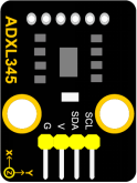
Connection Diagram
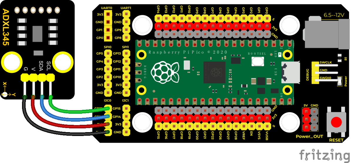
Run the sample code
Find adxl345_test.py, and then double-click to open the code. Before running the code, we need to import the clock module ADXL345.py.
We can save the following code directly on pico and name it ADXL345.py:
from machine import Pin
from machine import I2C
import time
import ustruct

DATA_FORMAT = 0x31
BW_RATE  = 0x2c
POWER_CTL = 0x2d
INT_ENABLE  = 0x2E
OFSX = 0x1e
OFSY =0x1f
OFSZ =0x20

class adxl345:
    def __init__(self, bus, scl, sda):
        self.bus = bus
        self.scl = scl
        self.sda = sda
        time.sleep(1)
        self.i2c = I2C(self.bus, scl = self.scl, sda = self.sda, freq = 10000)
        slv = self.i2c.scan()
        print(slv)
        for s in slv:
            buf = self.i2c.readfrom_mem(s, 0, 1)
            print(buf)
            if(buf[0] == 0xe5):
                self.slvAddr = s
                print('adxl345 found')
                print(self.slvAddr)
                print('adxl345 found')
                break
        #self.writeByte(POWER_CTL,0x00)  #sleep
        #time.sleep(0.001)
        #Low-level interrupt output, 13-bit full resolution, right-justified output data, 16g range
        self.writeByte(DATA_FORMAT,0x2B)
        #Data output speed is 100Hz
        self.writeByte(BW_RATE,0x0A)
        #do not use interrupts
        self.writeByte(INT_ENABLE,0x00)

        self.writeByte(OFSX,0x00)
        self.writeByte(OFSY,0x00)
        self.writeByte(OFSZ,0x00)
        #
        self.writeByte(POWER_CTL,0x28)
        time.sleep(1)

    def readXYZ(self):
        fmt = '<h' #little-endian
        buf1 = self.readByte(0x32)
        buf2 = self.readByte(0x33)
        buf = bytearray([buf1[0], buf2[0]])
        x, = ustruct.unpack(fmt, buf)
        x = x*3.9
        #print('x:',x)

        buf1 = self.readByte(0x34)
        buf2 = self.readByte(0x35)
        buf = bytearray([buf1[0], buf2[0]])
        y, = ustruct.unpack(fmt, buf)
        y = y*3.9
        #print('y:',y)

        buf1 = self.readByte(0x36)
        buf2 = self.readByte(0x37)
        buf = bytearray([buf1[0], buf2[0]])
        z, = ustruct.unpack(fmt, buf)
        z = z*3.9
        #print('z:',z)
        #print('************************')
        #time.sleep(0.5)
        return (x,y,z)

    def writeByte(self, addr, data):
        d = bytearray([data])
        self.i2c.writeto_mem(self.slvAddr, addr, d)
    def readByte(self, addr):
        return self.i2c.readfrom_mem(self.slvAddr, addr, 1)
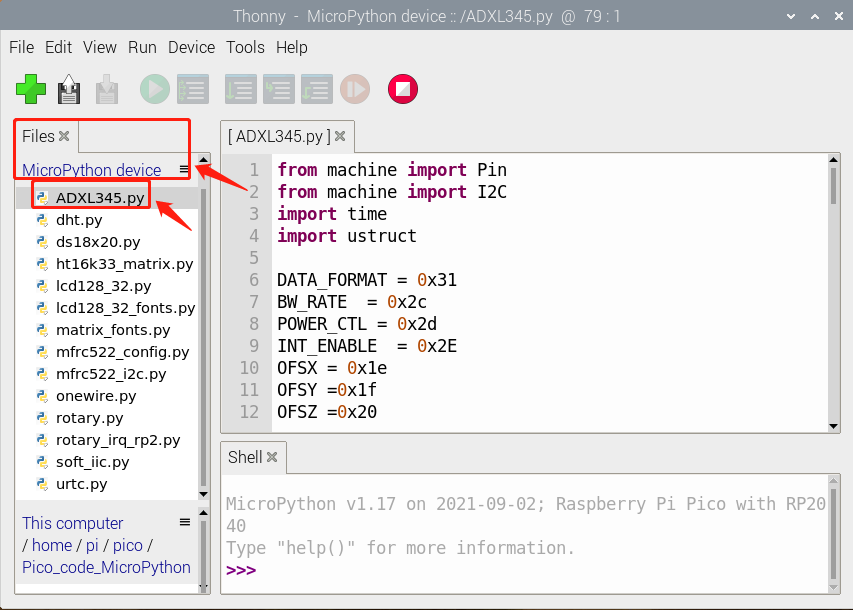
Then we execute adxl345_test.py:
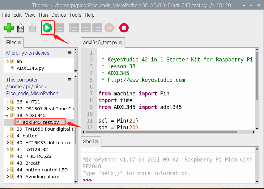
Code Explanation
Set IIC pins, select IIC0,sda–>20, scl–>21,then assign the value to x, y and z. The shell shows the value of x,y and z,unit is mg.
Test Result
Run the test code and watch the shell.
The shell displays the corresponding value of the three-axis acceleration in mg, as shown in the following figure.
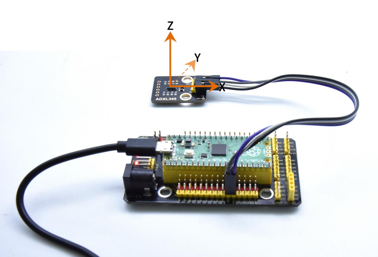
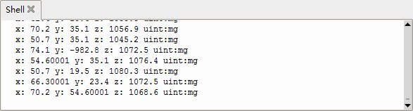
Test Code
'''
 * Keyestudio 42 in 1 Starter Kit for Raspberry Pi Pico
 * lesson 38
 * ADXL345
 * http://www.keyestudio.com
'''
from machine import Pin
import time
from ADXL345 import adxl345

scl = Pin(21)
sda = Pin(20)
bus = 0
snsr = adxl345(bus, scl, sda)
while True:
    x,y,z = snsr.readXYZ()
    print('x:',x,'y:',y,'z:',z,'uint:mg')
    time.sleep(0.1)
Project 39: TM1650 4-Digit Tube Display
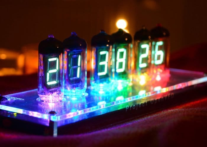
Overview
This module is mainly composed of a 0.36 inch red common anode 4-digit digital tube, and its driver chip is TM1650. When using it, we only need two signal lines to make the single-chip microcomputer control a 4-bitdigit tube, which greatly saves the IO port resources of the control board.
TM1650 is a special circuit for LED (light emitting diode display) drive control. It integrates MCU input and output control digital interface, data latch, LED drivers, keyboard scanning, brightness adjustment and other circuits.
TM1650 has stable performance, reliable quality and strong anti-interference ability.
It can be applied to the application of long-term continuous working for 24 hours.
TM1650 uses 2-wire serial transmission protocol for communication (note that this data transmission protocol is not a standard I2C protocol). The chip can drive the digital tube and save MCU pin resources through two pins and MCU communication.
Working Principle
TM1650 adopts IIC treaty and SDA and SCL wire.
Data command setting is 0x48. This means that lighting up the tube display not perform its button scanning function.
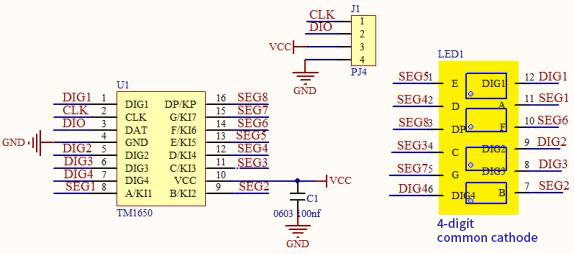
Data command setting: 0x48 means that we light up the digital tube, instead of enable the function of key scanning.
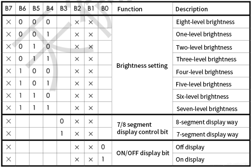
Command display setting:
bit[6:4]:set the brightness of tube display, and 000 is brightest
bit[3]:set to show decimal points
bit[0]:start the display of the tube display
Components
|
|
|
|---|---|---|
Raspberry Pi Pico Board*1 |
Raspberry Pi Pico Expansion Board*1 |
Keyestudio TM16504-Digit Segment Display*1 |
|
|
|
4P Dupont Wire*1 |
Micro USB Cable*1 |
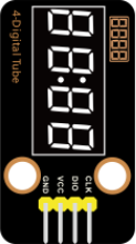
Run the test code
Double-click TM1650.p to open the code and click to run the code.
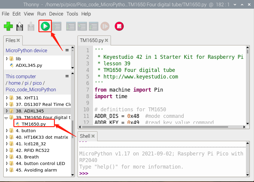
Connection Diagram
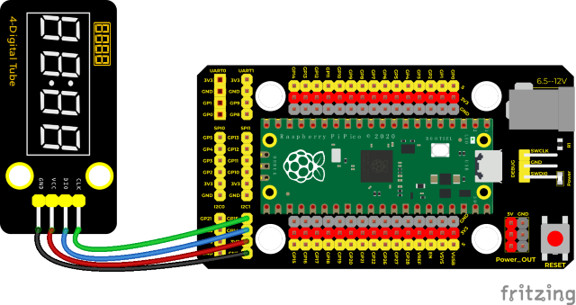
Test Code
'''
 * Keyestudio 42 in 1 Starter Kit for Raspberry Pi Pico
 * lesson 39
 * TM1650 Four digital tube
 * http://www.keyestudio.com
'''
from machine import Pin
import time

# definitions for TM1650
ADDR_DIS = 0x48  #mode command
ADDR_KEY = 0x49  #read key value command

# definitions for brightness
BRIGHT_DARKEST = 0
BRIGHT_TYPICAL = 2
BRIGHTEST      = 7

on  = 1
off = 0

# number:0~9
NUM = [0x3f,0x06,0x5b,0x4f,0x66,0x6d,0x7d,0x07,0x7f,0x6f]
# DIG = [0x68,0x6a,0x6c,0x6e]
DIG = [0x6e,0x6c,0x6a,0x68]
DOT = [0,0,0,0]

clkPin = 15
dioPin = 14
clk = machine.Pin(clkPin, machine.Pin.OUT)
dio = machine.Pin(dioPin, machine.Pin.OUT)

DisplayCommand = 0

def writeByte(wr_data):
    global clk,dio
    for i in range(8):
        if(wr_data & 0x80 == 0x80):
            dio.value(1)
        else:
            dio.value(0)
        clk.value(0)
        time.sleep(0.0001)
        clk.value(1)
        time.sleep(0.0001)
        clk.value(0)
        wr_data <<= 1
    return

def start():
    global clk,dio
    dio.value(1)
    clk.value(1)
    time.sleep(0.0001)
    dio.value(0)
    return

def ack():
    global clk,dio
    dy = 0
    clk.value(0)
    time.sleep(0.0001)
    dio = Pin(dioPin, machine.Pin.IN)
    while(dio.value() == 1):
        time.sleep(0.0001)
        dy += 1
        if(dy>5000):
            break
    clk.value(1)
    time.sleep(0.0001)
    clk.value(0)
    dio = Pin(dioPin, machine.Pin.OUT)
    return

def stop():
    global clk,dio
    dio.value(0)
    clk.value(1)
    time.sleep(0.0001)
    dio.value(1)
    return

def displayBit(bit, num):
    global ADDR_DIS
    if(num > 9 and bit > 4):
        return
    start()
    writeByte(ADDR_DIS)
    ack()
    writeByte(DisplayCommand)
    ack()
    stop()
    start()
    writeByte(DIG[bit-1])
    ack()
    if(DOT[bit-1] == 1):
        writeByte(NUM[num] | 0x80)
    else:
        writeByte(NUM[num])
    ack()
    stop()
    return

def clearBit(bit):
    if(bit > 4):
        return
    start()
    writeByte(ADDR_DIS)
    ack()
    writeByte(DisplayCommand)
    ack()
    stop()
    start()
    writeByte(DIG[bit-1])
    ack()
    writeByte(0x00)
    ack()
    stop()
    return


def setBrightness(b = BRIGHT_TYPICAL):
    global DisplayCommand,brightness
    DisplayCommand = (DisplayCommand & 0x0f)+(b<<4)
    return

def setMode(segment = 0):
    global DisplayCommand
    DisplayCommand = (DisplayCommand & 0xf7)+(segment<<3)
    return

def displayOnOFF(OnOff = 1):
    global DisplayCommand
    DisplayCommand = (DisplayCommand & 0xfe)+OnOff
    return

def displayDot(bit, OnOff):
    if(bit > 4):
        return
    if(OnOff == 1):
        DOT[bit-1] = 1;
    else:
        DOT[bit-1] = 0;
    return

def InitDigitalTube():
    setBrightness(2)
    setMode(0)
    displayOnOFF(1)
    for _ in range(4):
        clearBit(_)
    return

def ShowNum(num): #0~9999
    displayBit(1,num%10)
    if(num < 10):
        clearBit(2)
        clearBit(3)
        clearBit(4)
    if(num > 9 and num < 100):
        displayBit(2,num//10%10)
        clearBit(3)
        clearBit(4)
    if(num > 99 and num < 1000):
        displayBit(2,num//10%10)
        displayBit(3,num//100%10)
        clearBit(4)
    if(num > 999 and num < 10000):
        displayBit(2,num//10%10)
        displayBit(3,num//100%10)
        displayBit(4,num//1000)

InitDigitalTube()

while True:
    #displayDot(1,on)     # on or off, DigitalTube.Display(bit,number); bit=1---4  number=0---9
    for i in range(0,9999):
        ShowNum(i)
        time.sleep(0.01)
Code Explanation
1. clkPin = 15; dioPin = 14 is pin number. CLK is connected to GP15,DIO is connected to GOP14. We can set any pin at random.
2. displayBit(bit, num): show numbers at bit(1~4) bit num(0~9)
3. clearBit(bit): clear up bit(1~4)
4. setBrightness(): brightness setting
5. displayOnOFF() 0 means OFF, 1 means ON
6. displayDot(bit, OnOff) shows dots,0 means OFF, 1 means ON
7. ShowNum(num): show integer num,in the range of 0~9999
Test Result
Run the test code, wire up and power on. The 4-digit tube display will show integer from 0 to 99999, an increase of 1 for each 10ms, then start from 0 once reaching 99999.
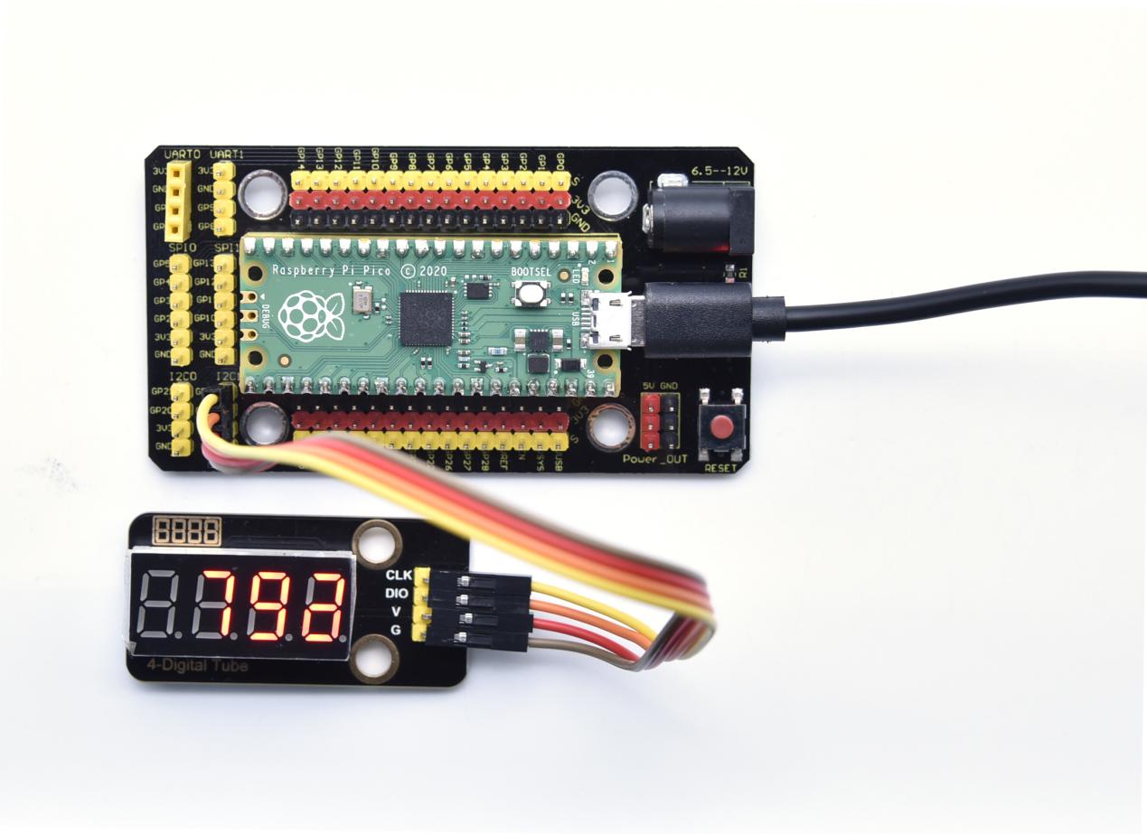
Project 40: HT16K33_8X8 Dot Matrix Module

Overview
What is the dot matrix display?
The 8X8 dot matrix is composed of 64 light-emitting diodes, and each light-emitting diode is placed at the intersection of the row line and the column line. When the corresponding row is set to 1 level, and a certain column is set to 0 level, the corresponding diode will light up.
Working Principle
As the schematic diagram shown, to light up the LED at the first row and column, we only need to set C1 to high level and R1 to low level. To turn on LEDs at the first row, we set R1 to low level and C1-C8 to high level.
16 IO ports are needed, which will highly waste the MCU resources.
Therefore, we designed this module, using the HT16K33 chip to drive an 8*8 dot matrix, which greatly saves the resources of the single-chip microcomputer.
There are three DIP switches on the module, all of which are set to I2C communication address. The setting method is shown below.
A0,A1and A2 are grounded, that is, the address is 0x70.
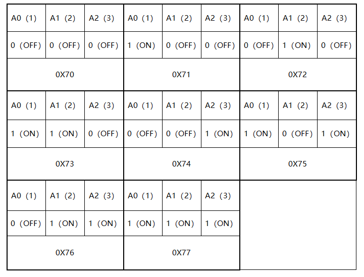
Components
|
|
|
|---|---|---|
Raspberry Pi Pico Board*1 |
Raspberry Pi Pico Expansion Board*1 |
Keyestudio HT16K33_8X8 Dot Matrix*1 |
|
|
|
4P Dupont Wire*1 |
Micro USB Cable*1 |
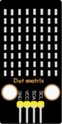
Connection Diagram
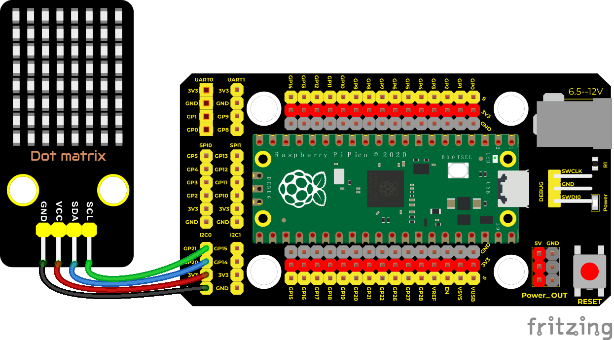
Run the test code
Save the following code to pico, import modules, name it as ht16k33_matrix.py:
ht16k33_matrix.py:
import machine
showbytes = 0
class ht16k33_matrix:

    _HT16K33_BLINK_CMD = const(0x80)
    _HT16K33_BLINK_DISPLAYON = const(0x01)
    _HT16K33_CMD_BRIGHTNESS = const(0xE0)
    _HT16K33_OSCILATOR_ON = const(0x21)

    def __init__(self,dt,clk,bus,addr):
        self.addr = addr
        self.i2c = machine.I2C(bus,sda=machine.Pin(dt),scl=machine.Pin(clk))
        self.setup()

    def setup(self):
        self.reg_write(_HT16K33_OSCILATOR_ON,0x00) # 00100001 turn on multiplexing
        self.reg_write(_HT16K33_BLINK_CMD | _HT16K33_BLINK_DISPLAYON,0x00)
        self.set_brightness(15)

    def show_char(self, c):
        bytes = bytearray()  # mutable binary data(byte)
        global showbytes
        for item in c:
            temp = item
            for i in range(8):
                if temp & 0x01:
                    showbytes |= 0x01
                showbytes <<= 1
                temp >>= 1
            bytes.append( ((showbytes & 0xFE)<<0)|((showbytes & 0x01)>>7) )  # The number of digits shifted to the right, and then judge 01
            #bytes.append((item & 0x01)<<7)
            bytes.append(0x00)
        self.i2c.writeto_mem(self.addr, 0x00, bytes)

    def set_brightness(self,brightness):
        self.reg_write(_HT16K33_CMD_BRIGHTNESS | brightness,0x00)

    def reg_write(self, reg, data):
        msg = bytearray()
        msg.append(data)
        self.i2c.writeto_mem(self.addr, reg, msg)
Then save the following code to pico and name it matrix_fonts.py
textFont1={
' ':[0x00, 0x00, 0x00, 0x00, 0x00, 0x00, 0x00, 0x00],
    '!':[0x18, 0x3c, 0x3c, 0x18, 0x18, 0x00, 0x18, 0x00],
    '"':[0x66, 0x66, 0x24, 0x00, 0x00, 0x00, 0x00, 0x00],
    '#':[0x6c, 0x6c, 0xfe, 0x6c, 0xfe, 0x6c, 0x6c, 0x00],
    '%':[0x00, 0xc6, 0xcc, 0x18, 0x30, 0x66, 0xc6, 0x00],
    '&':[0x38, 0x6c, 0x38, 0x76, 0xdc, 0xcc, 0x76, 0x00],
    '\'':[0x18, 0x18, 0x30, 0x00, 0x00, 0x00, 0x00, 0x00],
    '(':[0x0c, 0x18, 0x30, 0x30, 0x30, 0x18, 0x0c, 0x00],
    ')':[0x30, 0x18, 0x0c, 0x0c, 0x0c, 0x18, 0x30, 0x00],
    '*':[0x00, 0x66, 0x3c, 0xff, 0x3c, 0x66, 0x00, 0x00],
    '+':[0x00, 0x18, 0x18, 0x7e, 0x18, 0x18, 0x00, 0x00],
    '-':[0x00, 0x00, 0x00, 0x7e, 0x00, 0x00, 0x00, 0x00],
    '.':[0x00, 0x00, 0x00, 0x00, 0x00, 0x18, 0x18, 0x00],
    '/':[0x06, 0x0c, 0x18, 0x30, 0x60, 0xc0, 0x80, 0x00],
    '0':[0x7c, 0xc6, 0xce, 0xd6, 0xe6, 0xc6, 0x7c, 0x00],
    '1':[0x18, 0x38, 0x18, 0x18, 0x18, 0x18, 0x7e, 0x00],
    '2':[0x7c, 0xc6, 0x06, 0x1c, 0x30, 0x66, 0xfe, 0x00],
    '3':[0x7c, 0xc6, 0x06, 0x3c, 0x06, 0xc6, 0x7c, 0x00],
    '4':[0x1c, 0x3c, 0x6c, 0xcc, 0xfe, 0x0c, 0x1e, 0x00],
    '5':[0xfe, 0xc0, 0xc0, 0xfc, 0x06, 0xc6, 0x7c, 0x00],
    '6':[0x38, 0x60, 0xc0, 0xfc, 0xc6, 0xc6, 0x7c, 0x00],
    '7':[0xfe, 0xc6, 0x0c, 0x18, 0x30, 0x30, 0x30, 0x00],
    '8':[0x7c, 0xc6, 0xc6, 0x7c, 0xc6, 0xc6, 0x7c, 0x00],
    '9':[0x7c, 0xc6, 0xc6, 0x7e, 0x06, 0x0c, 0x78, 0x00],
    ':':[0x00, 0x18, 0x18, 0x00, 0x00, 0x18, 0x18, 0x00],
    ';':[0x7c, 0xc6, 0x0c, 0x18, 0x18, 0x00, 0x18, 0x00],
    '<':[0x06, 0x0c, 0x18, 0x30, 0x18, 0x0c, 0x06, 0x00],
    '=':[0x00, 0x00, 0x7e, 0x00, 0x00, 0x7e, 0x00, 0x00],
    '>':[0x60, 0x30, 0x18, 0x0c, 0x18, 0x30, 0x60, 0x00],
    '?':[0x7c, 0xc6, 0x0c, 0x18, 0x18, 0x00, 0x18, 0x00],
    '@':[0x7c, 0xc6, 0xde, 0xde, 0xde, 0xc0, 0x78, 0x00],
    'A':[0x38, 0x6c, 0xc6, 0xfe, 0xc6, 0xc6, 0xc6, 0x00],
    'B':[0xfc, 0x66, 0x66, 0x7c, 0x66, 0x66, 0xfc, 0x00],
    'C':[0x3c, 0x66, 0xc0, 0xc0, 0xc0, 0x66, 0x3c, 0x00],
    'D':[0xf8, 0x6c, 0x66, 0x66, 0x66, 0x6c, 0xf8, 0x00],
    'E':[0xfe, 0x62, 0x68, 0x78, 0x68, 0x62, 0xfe, 0x00],
    'F':[0xfe, 0x62, 0x68, 0x78, 0x68, 0x60, 0xf0, 0x00],
    'G':[0x3c, 0x66, 0xc0, 0xc0, 0xce, 0x66, 0x3a, 0x00],
    'H':[0xc6, 0xc6, 0xc6, 0xfe, 0xc6, 0xc6, 0xc6, 0x00],
    'I':[0x3c, 0x18, 0x18, 0x18, 0x18, 0x18, 0x3c, 0x00],
    'J':[0x1e, 0x0c, 0x0c, 0x0c, 0xcc, 0xcc, 0x78, 0x00],
    'K':[0xe6, 0x66, 0x6c, 0x78, 0x6c, 0x66, 0xe6, 0x00],
    'L':[0xf0, 0x60, 0x60, 0x60, 0x62, 0x66, 0xfe, 0x00],
    'M':[0xc6, 0xee, 0xfe, 0xfe, 0xd6, 0xc6, 0xc6, 0x00],
    'N':[0xc6, 0xe6, 0xf6, 0xde, 0xce, 0xc6, 0xc6, 0x00],
    'O':[0x7c, 0xc6, 0xc6, 0xc6, 0xc6, 0xc6, 0x7c, 0x00],
    'P':[0xfc, 0x66, 0x66, 0x7c, 0x60, 0x60, 0xf0, 0x00],
    'Q':[0x7c, 0xc6, 0xc6, 0xc6, 0xc6, 0xce, 0x7c, 0x0e],
    'R':[0xfc, 0x66, 0x66, 0x7c, 0x6c, 0x66, 0xe6, 0x00],
    'S':[0x7c, 0xc6, 0x60, 0x38, 0x0c, 0xc6, 0x7c, 0x00],
    'T':[0x7e, 0x7e, 0x5a, 0x18, 0x18, 0x18, 0x3c, 0x00],
    'U':[0xc6, 0xc6, 0xc6, 0xc6, 0xc6, 0xc6, 0x7c, 0x00],
    'V':[0xc6, 0xc6, 0xc6, 0xc6, 0xc6, 0x6c, 0x38, 0x00],
    'W':[0xc6, 0xc6, 0xc6, 0xd6, 0xd6, 0xfe, 0x6c, 0x00],
    'X':[0xc6, 0xc6, 0x6c, 0x38, 0x6c, 0xc6, 0xc6, 0x00],
    'Y':[0x66, 0x66, 0x66, 0x3c, 0x18, 0x18, 0x3c, 0x00],
    'Z':[0xfe, 0xc6, 0x8c, 0x18, 0x32, 0x66, 0xfe, 0x00],
    '[':[0x3c, 0x30, 0x30, 0x30, 0x30, 0x30, 0x3c, 0x00],
    '\\':[0xc0, 0x60, 0x30, 0x18, 0x0c, 0x06, 0x02, 0x00],
    ']':[0x3c, 0x0c, 0x0c, 0x0c, 0x0c, 0x0c, 0x3c, 0x00],
    '^':[0x10, 0x38, 0x6c, 0xc6, 0x00, 0x00, 0x00, 0x00],
    '_':[0x00, 0x00, 0x00, 0x00, 0x00, 0x00, 0x00, 0xff],
    '`':[0x30, 0x18, 0x0c, 0x00, 0x00, 0x00, 0x00, 0x00],
    'a':[0x00, 0x00, 0x78, 0x0c, 0x7c, 0xcc, 0x76, 0x00],
    'b':[0xe0, 0x60, 0x7c, 0x66, 0x66, 0x66, 0xdc, 0x00],
    'c':[0x00, 0x00, 0x7c, 0xc6, 0xc0, 0xc6, 0x7c, 0x00],
    'd':[0x1c, 0x0c, 0x7c, 0xcc, 0xcc, 0xcc, 0x76, 0x00],
    'e':[0x00, 0x00, 0x7c, 0xc6, 0xfe, 0xc0, 0x7c, 0x00],
    'f':[0x3c, 0x66, 0x60, 0xf8, 0x60, 0x60, 0xf0, 0x00],
    'g':[0x00, 0x00, 0x76, 0xcc, 0xcc, 0x7c, 0x0c, 0xf8],
    'h':[0xe0, 0x60, 0x6c, 0x76, 0x66, 0x66, 0xe6, 0x00],
    'i':[0x18, 0x00, 0x38, 0x18, 0x18, 0x18, 0x3c, 0x00],
    'j':[0x06, 0x00, 0x06, 0x06, 0x06, 0x66, 0x66, 0x3c],
    'k':[0xe0, 0x60, 0x66, 0x6c, 0x78, 0x6c, 0xe6, 0x00],
    'l':[0x38, 0x18, 0x18, 0x18, 0x18, 0x18, 0x3c, 0x00],
    'm':[0x00, 0x00, 0xec, 0xfe, 0xd6, 0xd6, 0xd6, 0x00],
    'n':[0x00, 0x00, 0xdc, 0x66, 0x66, 0x66, 0x66, 0x00],
    'o':[0x00, 0x00, 0x7c, 0xc6, 0xc6, 0xc6, 0x7c, 0x00],
    'p':[0x00, 0x00, 0xdc, 0x66, 0x66, 0x7c, 0x60, 0xf0],
    'q':[0x00, 0x00, 0x76, 0xcc, 0xcc, 0x7c, 0x0c, 0x1e],
    'r':[0x00, 0x00, 0xdc, 0x76, 0x60, 0x60, 0xf0, 0x00],
    's':[0x00, 0x00, 0x7e, 0xc0, 0x7c, 0x06, 0xfc, 0x00],
    't':[0x30, 0x30, 0xfc, 0x30, 0x30, 0x36, 0x1c, 0x00],
    'u':[0x00, 0x00, 0xcc, 0xcc, 0xcc, 0xcc, 0x76, 0x00],
    'v':[0x00, 0x00, 0xc6, 0xc6, 0xc6, 0x6c, 0x38, 0x00],
    'w':[0x00, 0x00, 0xc6, 0xd6, 0xd6, 0xfe, 0x6c, 0x00],
    'x':[0x00, 0x00, 0xc6, 0x6c, 0x38, 0x6c, 0xc6, 0x00],
    'y':[0x00, 0x00, 0xc6, 0xc6, 0xc6, 0x7e, 0x06, 0xfc],
    'z':[0x00, 0x00, 0x7e, 0x4c, 0x18, 0x32, 0x7e, 0x00],
    '{':[0x0e, 0x18, 0x18, 0x70, 0x18, 0x18, 0x0e, 0x00],
    '|':[0x18, 0x18, 0x18, 0x18, 0x18, 0x18, 0x18, 0x00],
    '}':[0x70, 0x18, 0x18, 0x0e, 0x18, 0x18, 0x70, 0x00],
    '~':[0x76, 0xdc, 0x00, 0x00, 0x00, 0x00, 0x00, 0x00],
}

eyes={
    'straight':[0x3c,0x7e,0xff,0xe7,0xe7,0xff,0x7e,0x3c],
    'straightX2':[0x3c,0x7e,0xe7,0xc3,0xc3,0xe7,0x7e,0x3c],
    'straightX3':[0x3c,0x66,0xc3,0x81,0x81,0xc3,0x66,0x3c],
    'straightX4':[0x3c,0x42,0x81,0x81,0x81,0x81,0x42,0x3c],
    'straightX2Left1':[0x3c,0x7e,0xcf,0x87,0x87,0xcf,0x7e,0x3c],
    'straightX2Left2':[0x3c,0x7e,0x9f,0x0f,0x0f,0x9f,0x7e,0x3c],
    'straightX2Left3':[0x3c,0x7e,0x3f,0x1f,0x1f,0x3f,0x7e,0x3c],
    'straightX2Left4':[0x3c,0x7e,0x7f,0x3f,0x3f,0x7f,0x7e,0x3c],
    'straightX2Left5':[0x3c,0x7e,0xff,0x7f,0x7f,0xff,0x7e,0x3c],
    'straightR2':[0x3c,0x7e,0xe7,0xdb,0xdb,0xe7,0x7e,0x3c],
    'noEyeball':[0x3c,0x7e,0xff,0xff,0xff,0xff,0x7e,0x3c],
    'straightBlink1':[0x00,0x7e,0xff,0xe7,0xe7,0xff,0x7e,0x00],
    'straightBlink2':[0x00,0x00,0xff,0xe7,0xe7,0xff,0x00,0x00],
    'straightBlink3':[0x00,0x00,0x00,0xe7,0xe7,0x00,0x00,0x00],
    'straightBlinkLine':[0x00,0x00,0x00,0xff,0xff,0x00,0x00,0x00],
    'all_off':[0x00,0x00,0x00,0x00,0x00,0x00,0x00,0x00],
    'up1':[0x3c,0x7e,0xe7,0xe7,0xff,0xff,0x7e,0x3c],
    'up2':[0x3c,0x66,0xe7,0xff,0xff,0xff,0x7e,0x3c],
    'up3':[0x24,0x66,0xff,0xff,0xff,0xff,0x7e,0x3c],
    'up4':[0x24,0x7e,0xff,0xff,0xff,0xff,0x7e,0x3c],
    'upLeft':[0x3c,0x4e,0xcf,0xff,0xff,0xff,0x7e,0x3c],
    'upLeft1':[0x3c,0x7e,0x9f,0x9f,0xff,0xff,0x7e,0x3c],
    'upLeft2':[0x3c,0x1e,0x9f,0xff,0xff,0xff,0x7e,0x3c],
    'upRight1':[0x3c,0x7e,0xf9,0xf9,0xff,0xff,0x7e,0x3c],
    'upRight':[0x3c,0x72,0xf3,0xff,0xff,0xff,0x7e,0x3c],
    'down1':[0x3c,0x7e,0xff,0xff,0xe7,0xe7,0x7e,0x3c],
    'down2':[0x3c,0x7e,0xff,0xff,0xff,0xe7,0x66,0x3c],
    'down3':[0x3c,0x7e,0xff,0xff,0xff,0xe7,0x66,0x3c],
    'down4':[0x3c,0x7e,0xff,0xff,0xff,0xff,0x7e,0x24],
    'downRight':[0x3c,0x7e,0xff,0xff,0xf9,0xf9,0x7e,0x3c],
    'downRight1':[0x3c,0x7e,0xff,0xff,0xff,0xf3,0x72,0x3c],
    'downRight2':[0x3c,0x7e,0xff,0xff,0xff,0xf9,0x78,0x3c],
    'downLeft':[0x3c,0x7e,0xff,0xff,0xff,0xcf,0x4e,0x3c],
    'downLeftB':[0x3c,0x7e,0xff,0xff,0x9f,0x9f,0x7e,0x3c],
    'downLeft1':[0x3c,0x7e,0xff,0xff,0xcf,0xcf,0x7e,0x3c],
    'downLeft1Blink1':[0x00,0x7e,0xff,0xff,0xcf,0xcf,0x7e,0x00],
    'downLeft1Blink2':[0x00,0x00,0xff,0xff,0xcf,0xcf,0x00,0x00],
    'downLeft1Blink3':[0x00,0x00,0x00,0xff,0xcf,0x00,0x00,0x00],
    'downLeft2':[0x3c,0x7e,0xff,0xff,0xff,0x9f,0x1e,0x3c],
    'left1':[0x3c,0x7e,0xff,0xcf,0xcf,0xff,0x7e,0x3c],
    'left2':[0x3c,0x7e,0xff,0x9f,0x9f,0xff,0x7e,0x3c],
    'left3':[0x3c,0x7e,0xff,0x3f,0x3f,0xff,0x7e,0x3c],
    'left4':[0x3c,0x7e,0xff,0x7f,0x7f,0xff,0x7e,0x3c],
    'right1':[0x3c,0x7e,0xff,0xf3,0xf3,0xff,0x7e,0x3c],
    'right2':[0x3c,0x7e,0xff,0xf9,0xf9,0xff,0x7e,0x3c],
    'right3':[0x3c,0x7e,0xff,0xfc,0xfc,0xff,0x7e,0x3c],
    'right4':[0x3c,0x7e,0xff,0xfe,0xfe,0xff,0x7e,0x3c],
    'ghost1':[0x3c,0x56,0x93,0xdb,0xff,0xff,0xdd,0x89],
    'ghost2':[0x38,0x7c,0x92,0x92,0xfe,0xfe,0xfe,0xaa],

}

shapes={
    'smile':[0x3c, 0x42, 0xa5, 0x81, 0xa5, 0x99, 0x42, 0x3c],
    'smileL':[0x3c, 0x42, 0xa9, 0xa9, 0x85, 0xb9, 0x42, 0x3c],
    'empty':[0x00,0x00,0x00,0x00,0x00,0x00,0x00,0x00],
    'all_on':[0xff,0xff,0xff,0xff,0xff,0xff,0xff,0xff],
    'arrow':[0x18,0x24,0x42,0xff,0x18,0x18,0x18,0x18],
    'invader1':[0x18,0x3c,0x7e,0xdb,0xff,0x24,0x5a,0xa5],
    'invader2':[0x18,0x3c,0x7e,0xdb,0xff,0x24,0x5a,0x42],
    'tree1':[0x18, 0x18, 0x3c, 0x3c, 0x7e, 0xff, 0x18, 0x18],
    'tree1lit1':[0x18, 0x18, 0x3c, 0x3c, 0x7e, 0xff, 0x18, 0x18],
    'tree1lit2':[0x5a,0x99,0x3c,0xbd,0x7e,0xff,0x18,0x18],
    'tree2':[0x18, 0x18, 0x3c, 0x3c, 0x7e, 0x7e, 0xff, 0x18],
    'bunny1':[0x66, 0x66, 0x66, 0xff, 0x81, 0xa5, 0x99, 0x7e],
    'bunny2':[0x66, 0xe7, 0x66, 0xff, 0x81, 0xa5, 0x99, 0x7e],
    'bunny3':[0x66, 0x66, 0xff, 0x81, 0xa5, 0x81, 0x99, 0x7e],
    'danbo':[0x00, 0xff, 0x81, 0xa5, 0x81, 0x81, 0xff, 0x00],
    'clock1':[0x3c, 0x42, 0x91, 0x91, 0x9d, 0x81, 0x42, 0x3c],
    'heart1F':[0x00, 0x66, 0xff, 0xff, 0x7e, 0x3c, 0x18, 0x00],
    'heart1':[0x00, 0x66, 0x99, 0x81, 0x42, 0x24, 0x18, 0x00],
    'heart2':[0x00, 0x66, 0x99, 0x81, 0x81, 0x42, 0x24, 0x18],
    'heart2F':[0x00, 0x66, 0xff, 0xff, 0xff, 0x7e, 0x3c, 0x18],
    'santaHat':[0x00, 0x3c, 0x7e, 0x4f, 0xef, 0xef, 0xef, 0x0f],
    'santaHat2':[0x00,0x00,0x3c,0x7e,0x4f,0xef,0xef,0xef],
    'star1':[0x00,0x00,0x00,0x18,0x18,0x00,0x00,0x00],
    'star2':[0x00,0x00,0x24,0x18,0x18,0x24,0x00,0x00],
    'star3':[0x00,0x42,0x24,0x18,0x18,0x24,0x42,0x00],
    'star4':[0x81,0x42,0x24,0x18,0x18,0x24,0x42,0x81],
    'star5':[0x02,0x84,0x48,0x38,0x1c,0x12,0x21,0x40],
    'star6':[0x06,0x8c,0xd8,0x7c,0x3e,0x1b,0x31,0x60],
    'star7':[0x04,0x08,0x90,0x5c,0x3a,0x09,0x10,0x20],
    'star8':[0x08,0x10,0x10,0x9e,0x79,0x08,0x08,0x10],
    'star9':[0x10,0x10,0x10,0x1f,0xf8,0x08,0x08,0x08],
    'star10':[0x20,0x10,0x11,0x1e,0x78,0x88,0x08,0x04],
    'star11':[0x40,0x21,0x12,0x1c,0x38,0x48,0x84,0x02],

}
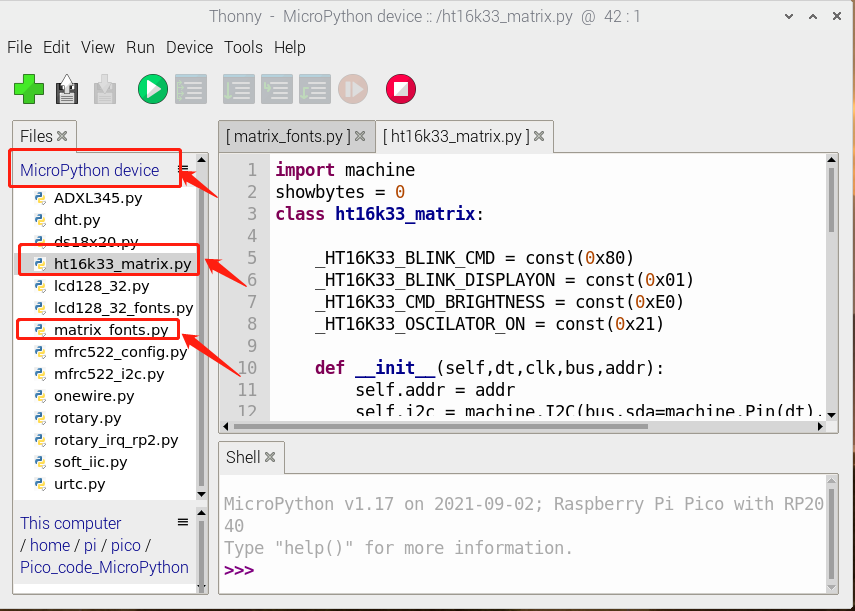
Then we find matrix dot.py in the code path we saved, then double-click to open the code, and then click  to run the code.
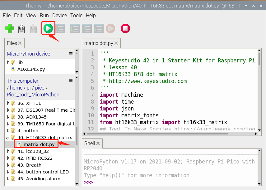
Test Code
'''
 * * Keyestudio 42 in 1 Starter Kit for Raspberry Pi Pico
 * lesson 40
 * HT16K33 8*8 dot matrix
 * http://www.keyestudio.com
'''
import machine
import time
import json
import matrix_fonts
from ht16k33_matrix import ht16k33_matrix
## Tool To Make Sprites https://gurgleapps.com/tools/matrix
#i2c config
clock_pin = 21
data_pin = 20
bus = 0
i2c_addr_left = 0x70
use_i2c = True

def scan_for_devices():
    i2c = machine.I2C(bus,sda=machine.Pin(data_pin),scl=machine.Pin(clock_pin))
    devices = i2c.scan()
    if devices:
        for d in devices:
            print(hex(d))
    else:
        print('no i2c devices')

if use_i2c:
    scan_for_devices()
    left_eye = ht16k33_matrix(data_pin, clock_pin, bus, i2c_addr_left)

def show_char(left):
    if use_i2c:
        left_eye.show_char(left)

def scroll_message(font,message='hello',delay=0.05):
    left_message = '   ' + message
    right_message = message + '   '
    length=len(right_message)
    char_range=range(length-1)
    for char_pos in char_range:
      right_left_char=font[right_message[char_pos]]
      right_right_char=font[right_message[char_pos+1]]
      left_left_char=font[left_message[char_pos]]
      left_right_char=font[left_message[char_pos+1]]
      for shift in range(8):
        left_bytes=[0,0,0,0,0,0,0,0]
        right_bytes=[0,0,0,0,0,0,0,0]
        for col in range(8):
          left_bytes[col]=left_bytes[col]|left_left_char[col]<<shift
          left_bytes[col]=left_bytes[col]|left_right_char[col]>>8-shift;
          right_bytes[col]=right_bytes[col]|right_left_char[col]<<shift
          right_bytes[col]=right_bytes[col]|right_right_char[col]>>8-shift;
        if use_i2c:
                left_eye.show_char(left_bytes)
        time.sleep(delay)


while True:
    show_char(matrix_fonts.textFont1['A'])
    time.sleep(1)
    show_char(matrix_fonts.textFont1['B'])
    time.sleep(1)
    show_char(matrix_fonts.textFont1['C'])
    time.sleep(1)
    scroll_message(matrix_fonts.textFont1, ' Hello World ')
Code Explanation
show_char(): displayed characters, for instance show_char(matrix_fonts.textFont1[‘A’]) shows A
scroll_message(font,message=’hello’,delay=0.05): scroll to display, 0.05 is the speed of the scroll, massage is character string and font is module file.
Test Result
Wire up and run the test code. The dot matrix displays “A” for one second, “B” for one second, “C” for one second, and then scroll to display the “Hello World” pattern.
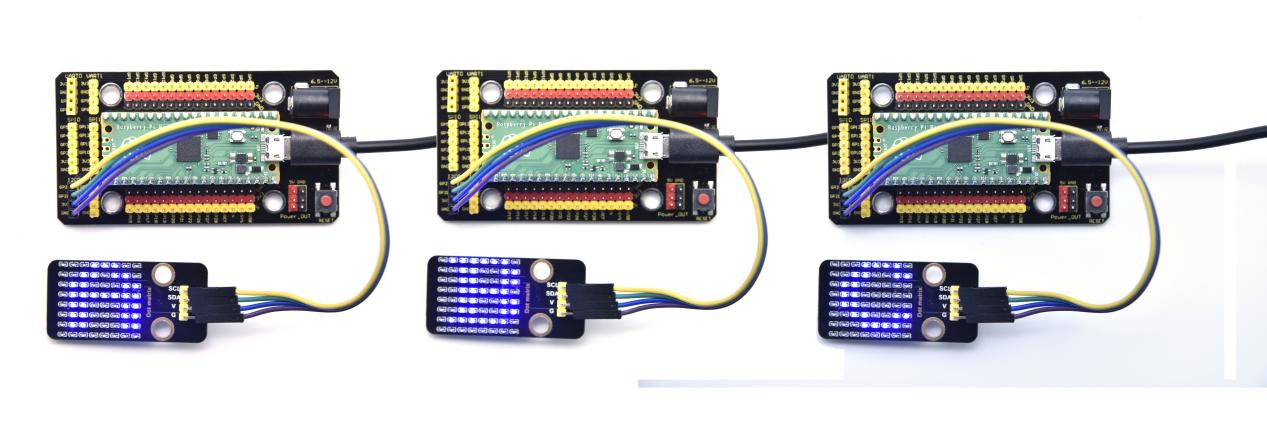
Project 41: LCD_128X32_DOT Module
Description

This is a 128*32 pixel LCD module, which uses IIC communication mode and ST7567A driver chip . At the same time, the code contains all the English letters and common symbols of the library that can be directly called. When used, we can also set English letters and symbols to display different text sizes in our code. To make it easy to set up the pattern display, we also provide a mold capture software that can convert a specific pattern into control code and then copy it directly into the test code for use.
In the experiment, we will set up the display screen to display various English words, common symbols and numbers.
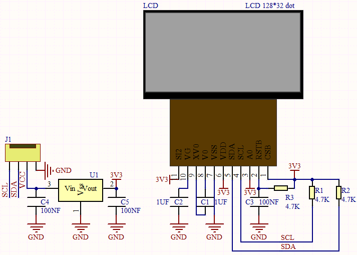
Required Components
|
|
|
|---|---|---|
Raspberry Pi Pico Board*1 |
Raspberry Pi Pico Expansion Board*1 |
Keyestudio LCD_128X32_DOT Module*1 |
|
|
|
4P Dupont Wire*1 |
Micro USB Cable*1 |
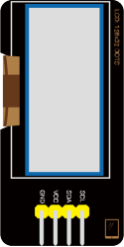
Connection Diagram
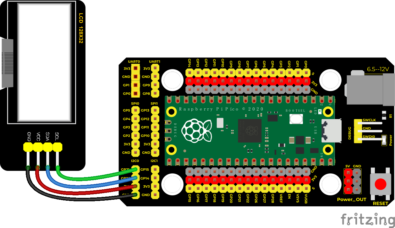
Run the test code
We need to save the following code in the pico and name lcd128_32.py.
"""
Micropython (Raspberry Pi Pico)
2022/1/12     DENGFEI
lcd.Display() Can only display 94 limited characters in fonts
"""

import machine
import time
import lcd128_32_fonts
cursor = [0, 0]
class lcd128_32:

    def __init__(self,dt,clk,bus,addr):
        self.addr = addr
        self.i2c = machine.I2C(bus,sda=machine.Pin(dt),scl=machine.Pin(clk))
        self.Init()

    def WriteByte_command(self, cmd):
        self.reg_write(0x00, cmd)

    def WriteByte_dat(self, dat):
        self.reg_write(0x40, dat)

    def reg_write(self, reg, data):
        msg = bytearray()
        msg.append(data)
        self.i2c.writeto_mem(self.addr, reg, msg)

    def Init(self):
        #self.i2c.start()
        time.sleep(0.01)
        self.WriteByte_command(0xe2)
        time.sleep(0.01)
        self.WriteByte_command(0xa3)
        self.WriteByte_command(0xa0)
        self.WriteByte_command(0xc8)
        self.WriteByte_command(0x22)
        self.WriteByte_command(0x81)
        self.WriteByte_command(0x30)
        self.WriteByte_command(0x2c)
        self.WriteByte_command(0x2e)
        self.WriteByte_command(0x2f)
        self.Clear()
        self.WriteByte_command(0xff)
        self.WriteByte_command(0x72)
        self.WriteByte_command(0xfe)
        self.WriteByte_command(0xd6)
        self.WriteByte_command(0x90)
        self.WriteByte_command(0x9d)
        self.WriteByte_command(0xaf)
        self.WriteByte_command(0x40)

    def Clear(self):
        for i in range(4):
            self.WriteByte_command(0xb0 + i)
            self.WriteByte_command(0x10)
            self.WriteByte_command(0x00)
            for j in range(128):
                self.WriteByte_dat(0x00)

    def Cursor(self, y, x):
        if x > 17:
            x = 17
        if y > 3:
            x = 3
        cursor[0] = y
        cursor[1] = x

    def WriteFont(self, num):
        for item in lcd128_32_fonts.textFont[num]:
            self.WriteByte_dat(item)

    def Display(self, str):
        self.WriteByte_command(0xb0 + cursor[0])
        self.WriteByte_command(0x10 + cursor[1] * 7 // 16)
        self.WriteByte_command(0x00 + cursor[1] * 7 % 16)
        for num in range(len(str)):
            if str[num] == '0':
                self.WriteFont(0)
            elif str[num] == '1':
                self.WriteFont(1)
            elif str[num] == '2':
                self.WriteFont(2)
            elif str[num] == '3':
                self.WriteFont(3)
            elif str[num] == '4':
                self.WriteFont(4)
            elif str[num] == '5':
                self.WriteFont(5)
            elif str[num] == '6':
                self.WriteFont(6)
            elif str[num] == '7':
                self.WriteFont(7)
            elif str[num] == '8':
                self.WriteFont(8)
            elif str[num] == '9':
                self.WriteFont(9)
            elif str[num] == 'a':
                self.WriteFont(10)
            elif str[num] == 'b':
                self.WriteFont(11)
            elif str[num] == 'c':
                self.WriteFont(12)
            elif str[num] == 'd':
                self.WriteFont(13)
            elif str[num] == 'e':
                self.WriteFont(14)
            elif str[num] == 'f':
                self.WriteFont(15)
            elif str[num] == 'g':
                self.WriteFont(16)
            elif str[num] == 'h':
                self.WriteFont(17)
            elif str[num] == 'i':
                self.WriteFont(18)
            elif str[num] == 'j':
                self.WriteFont(19)
            elif str[num] == 'k':
                self.WriteFont(20)
            elif str[num] == 'l':
                self.WriteFont(21)
            elif str[num] == 'm':
                self.WriteFont(22)
            elif str[num] == 'n':
                self.WriteFont(23)
            elif str[num] == 'o':
                self.WriteFont(24)
            elif str[num] == 'p':
                self.WriteFont(25)
            elif str[num] == 'q':
                self.WriteFont(26)
            elif str[num] == 'r':
                self.WriteFont(27)
            elif str[num] == 's':
                self.WriteFont(28)
            elif str[num] == 't':
                self.WriteFont(29)
            elif str[num] == 'u':
                self.WriteFont(30)
            elif str[num] == 'v':
                self.WriteFont(31)
            elif str[num] == 'w':
                self.WriteFont(32)
            elif str[num] == 'x':
                self.WriteFont(33)
            elif str[num] == 'y':
                self.WriteFont(34)
            elif str[num] == 'z':
                self.WriteFont(35)
            elif str[num] == 'A':
                self.WriteFont(36)
            elif str[num] == 'B':
                self.WriteFont(37)
            elif str[num] == 'C':
                self.WriteFont(38)
            elif str[num] == 'D':
                self.WriteFont(39)
            elif str[num] == 'E':
                self.WriteFont(40)
            elif str[num] == 'F':
                self.WriteFont(41)
            elif str[num] == 'G':
                self.WriteFont(42)
            elif str[num] == 'H':
                self.WriteFont(43)
            elif str[num] == 'I':
                self.WriteFont(44)
            elif str[num] == 'J':
                self.WriteFont(45)
            elif str[num] == 'K':
                self.WriteFont(46)
            elif str[num] == 'L':
                self.WriteFont(47)
            elif str[num] == 'M':
                self.WriteFont(48)
            elif str[num] == 'N':
                self.WriteFont(49)
            elif str[num] == 'O':
                self.WriteFont(50)
            elif str[num] == 'P':
                self.WriteFont(51)
            elif str[num] == 'Q':
                self.WriteFont(52)
            elif str[num] == 'R':
                self.WriteFont(53)
            elif str[num] == 'S':
                self.WriteFont(54)
            elif str[num] == 'T':
                self.WriteFont(55)
            elif str[num] == 'U':
                self.WriteFont(56)
            elif str[num] == 'V':
                self.WriteFont(57)
            elif str[num] == 'W':
                self.WriteFont(58)
            elif str[num] == 'X':
                self.WriteFont(59)
            elif str[num] == 'Y':
                self.WriteFont(60)
            elif str[num] == 'Z':
                self.WriteFont(61)
            elif str[num] == '!':
                self.WriteFont(62)
            elif str[num] == '"':
                self.WriteFont(63)
            elif str[num] == '#':
                self.WriteFont(64)
            elif str[num] == '$':
                self.WriteFont(65)
            elif str[num] == '%':
                self.WriteFont(66)
            elif str[num] == '&':
                self.WriteFont(67)
            elif str[num] == '\'':
                self.WriteFont(68)
            elif str[num] == '(':
                self.WriteFont(69)
            elif str[num] == ')':
                self.WriteFont(70)
            elif str[num] == '*':
                self.WriteFont(71)
            elif str[num] == '+':
                self.WriteFont(72)
            elif str[num] == ',':
                self.WriteFont(73)
            elif str[num] == '-':
                self.WriteFont(74)
            elif str[num] == '/':
                self.WriteFont(75)
            elif str[num] == ':':
                self.WriteFont(76)
            elif str[num] == ';':
                self.WriteFont(77)
            elif str[num] == '<':
                self.WriteFont(78)
            elif str[num] == '=':
                self.WriteFont(79)
            elif str[num] == '>':
                self.WriteFont(80)
            elif str[num] == '?':
                self.WriteFont(81)
            elif str[num] == '@':
                self.WriteFont(82)
            elif str[num] == '{':
                self.WriteFont(83)
            elif str[num] == '|':
                self.WriteFont(84)
            elif str[num] == '}':
                self.WriteFont(85)
            elif str[num] == '~':
                self.WriteFont(86)
            elif str[num] == ' ':
                self.WriteFont(87)
            elif str[num] == '.':
                self.WriteFont(88)
            elif str[num] == '^':
                self.WriteFont(89)
            elif str[num] == '_':
                self.WriteFont(90)
            elif str[num] == '`':
                self.WriteFont(91)
            elif str[num] == '[':
                self.WriteFont(92)
            elif str[num] == '\\':
                self.WriteFont(93)
            elif str[num] == ']':
                self.WriteFont(94)
Then save the following code to pico and name it lcd128_32_fonts.py
"""
Micropython (Raspberry Pi Pico)
Include 94 characters
"""
textFont={
    0:[0x00, 0x3E, 0x51, 0x49, 0x45, 0x3E, 0x00],
    1:[0x00, 0x00, 0x42, 0x7F, 0x40, 0x00, 0x00],
    2:[0x00, 0x62, 0x51, 0x49, 0x49, 0x46, 0x00],
    3:[0x00, 0x21, 0x41, 0x49, 0x4D, 0x33, 0x00],
    4:[0x00, 0x18, 0x14, 0x12, 0x7F, 0x10, 0x00],
    5:[0x00, 0x27, 0x45, 0x45, 0x45, 0x39, 0x00],
    6:[0x00, 0x3C, 0x4A, 0x49, 0x49, 0x31, 0x00],
    7:[0x00, 0x01, 0x71, 0x09, 0x05, 0x03, 0x00],
    8:[0x00, 0x36, 0x49, 0x49, 0x49, 0x36, 0x00],
    9:[0x00, 0x46, 0x49, 0x49, 0x29, 0x1E, 0x00],
    10:[0x00, 0x24, 0x54, 0x54, 0x38, 0x40, 0x00],
    11:[0x00, 0x7F, 0x28, 0x44, 0x44, 0x38, 0x00],
    12:[0x00, 0x38, 0x44, 0x44, 0x44, 0x08, 0x00],
    13:[0x00, 0x38, 0x44, 0x44, 0x28, 0x7F, 0x00],
    14:[0x00, 0x38, 0x54, 0x54, 0x54, 0x08, 0x00],
    15:[0x00, 0x08, 0x7E, 0x09, 0x09, 0x02, 0x00],
    16:[0x00, 0x98, 0xA4, 0xA4, 0xA4, 0x78, 0x00],
    17:[0x00, 0x7F, 0x08, 0x04, 0x04, 0x78, 0x00],
    18:[0x00, 0x00, 0x00, 0x79, 0x00, 0x00, 0x00],
    19:[0x00, 0x00, 0x80, 0x88, 0x79, 0x00, 0x00],
    20:[0x00, 0x7F, 0x10, 0x28, 0x44, 0x40, 0x00],
    21:[0x00, 0x00, 0x41, 0x7F, 0x40, 0x00, 0x00],
    22:[0x00, 0x78, 0x04, 0x78, 0x04, 0x78, 0x00],
    23:[0x00, 0x04, 0x78, 0x04, 0x04, 0x78, 0x00],
    24:[0x00, 0x38, 0x44, 0x44, 0x44, 0x38, 0x00],
    25:[0x00, 0xFC, 0x24, 0x24, 0x24, 0x18, 0x00],
    26:[0x00, 0x18, 0x24, 0x24, 0x24, 0xFC, 0x00],
    27:[0x00, 0x04, 0x78, 0x04, 0x04, 0x08, 0x00],
    28:[0x00, 0x48, 0x54, 0x54, 0x54, 0x24, 0x00],
    29:[0x00, 0x04, 0x3F, 0x44, 0x44, 0x24, 0x00],
    30:[0x00, 0x3C, 0x40, 0x40, 0x3C, 0x40, 0x00],
    31:[0x00, 0x1C, 0x20, 0x40, 0x20, 0x1C, 0x00],
    32:[0x00, 0x3C, 0x40, 0x3C, 0x40, 0x3C, 0x00],
    33:[0x00, 0x44, 0x28, 0x10, 0x28, 0x44, 0x00],
    34:[0x00, 0x9C, 0xA0, 0xA0, 0x90, 0x7C, 0x00],
    35:[0x00, 0x44, 0x64, 0x54, 0x4C, 0x44, 0x00],
    36:[0x00, 0x7C, 0x12, 0x11, 0x12, 0x7C, 0x00],
    37:[0x00, 0x7F, 0x49, 0x49, 0x49, 0x36, 0x00],
    38:[0x00, 0x3E, 0x41, 0x41, 0x41, 0x22, 0x00],
    39:[0x00, 0x7F, 0x41, 0x41, 0x41, 0x3E, 0x00],
    40:[0x00, 0x7F, 0x49, 0x49, 0x49, 0x41, 0x00],
    41:[0x00, 0x7F, 0x09, 0x09, 0x09, 0x01, 0x00],
    42:[0x00, 0x3E, 0x41, 0x51, 0x51, 0x72, 0x00],
    43:[0x00, 0x7F, 0x08, 0x08, 0x08, 0x7F, 0x00],
    44:[0x00, 0x00, 0x41, 0x7F, 0x41, 0x00, 0x00],
    45:[0x00, 0x20, 0x40, 0x41, 0x3F, 0x01, 0x00],
    46:[0x00, 0x7F, 0x08, 0x14, 0x22, 0x41, 0x00],
    47:[0x00, 0x7F, 0x40, 0x40, 0x40, 0x40, 0x00],
    48:[0x00, 0x7F, 0x02, 0x0C, 0x02, 0x7F, 0x00],
    49:[0x00, 0x7F, 0x04, 0x08, 0x10, 0x7F, 0x00],
    50:[0x00, 0x3E, 0x41, 0x41, 0x41, 0x3E, 0x00],
    51:[0x00, 0x7F, 0x09, 0x09, 0x09, 0x06, 0x00],
    52:[0x00, 0x3E, 0x41, 0x51, 0x21, 0x5E, 0x00],
    53:[0x00, 0x7F, 0x09, 0x19, 0x29, 0x46, 0x00],
    54:[0x00, 0x26, 0x49, 0x49, 0x49, 0x32, 0x00],
    55:[0x00, 0x01, 0x01, 0x7F, 0x01, 0x01, 0x00],
    56:[0x00, 0x3F, 0x40, 0x40, 0x40, 0x3F, 0x00],
    57:[0x00, 0x1F, 0x20, 0x40, 0x20, 0x1F, 0x00],
    58:[0x00, 0x7F, 0x20, 0x18, 0x20, 0x7F, 0x00],
    59:[0x00, 0x63, 0x14, 0x08, 0x14, 0x63, 0x00],
    60:[0x00, 0x03, 0x04, 0x78, 0x04, 0x03, 0x00],
    61:[0x00, 0x61, 0x51, 0x49, 0x45, 0x43, 0x00],
    62:[0x00, 0x00, 0x00, 0x5F, 0x00, 0x00, 0x00],
    63:[0x00, 0x00, 0x07, 0x00, 0x07, 0x00, 0x00],
    64:[0x00, 0x14, 0x7F, 0x14, 0x7F, 0x14, 0x00],
    65:[0x00, 0x24, 0x2E, 0x7B, 0x2A, 0x12, 0x00],
    66:[0x00, 0x23, 0x13, 0x08, 0x64, 0x62, 0x00],
    67:[0x00, 0x36, 0x49, 0x56, 0x20, 0x50, 0x00],
    68:[0x00, 0x00, 0x04, 0x03, 0x01, 0x00, 0x00],
    69:[0x00, 0x00, 0x1C, 0x22, 0x41, 0x00, 0x00],
    70:[0x00, 0x00, 0x41, 0x22, 0x1C, 0x00, 0x00],
    71:[0x00, 0x22, 0x14, 0x7F, 0x14, 0x22, 0x00],
    72:[0x00, 0x08, 0x08, 0x7F, 0x08, 0x08, 0x00],
    73:[0x00, 0x40, 0x30, 0x10, 0x00, 0x00, 0x00],
    74:[0x00, 0x08, 0x08, 0x08, 0x08, 0x08, 0x00],
    75:[0x00, 0x20, 0x10, 0x08, 0x04, 0x02, 0x00],
    76:[0x00, 0x00, 0x36, 0x36, 0x00, 0x00, 0x00],
    77:[0x00, 0x40, 0x36, 0x36, 0x00, 0x00, 0x00],
    78:[0x00, 0x08, 0x14, 0x22, 0x41, 0x00, 0x00],
    79:[0x00, 0x14, 0x14, 0x14, 0x14, 0x14, 0x00],
    80:[0x00, 0x00, 0x41, 0x22, 0x14, 0x08, 0x00],
    81:[0x00, 0x02, 0x01, 0x59, 0x05, 0x02, 0x00],
    82:[0x00, 0x3E, 0x41, 0x5D, 0x55, 0x5E, 0x00],
    83:[0x00, 0x08, 0x36, 0x41, 0x00, 0x00, 0x00],
    84:[0x00, 0x00, 0x00, 0x77, 0x00, 0x00, 0x00],
    85:[0x00, 0x00, 0x00, 0x41, 0x36, 0x08, 0x00],
    86:[0x00, 0x08, 0x04, 0x08, 0x10, 0x08, 0x00],
    87:[0x00, 0x00, 0x00, 0x00, 0x00, 0x00, 0x00],
    88:[0x00, 0x00, 0x60, 0x60, 0x00, 0x00, 0x00],
    89:[0x00, 0x04, 0x02, 0x7F, 0x02, 0x04, 0x00],
    90:[0x00, 0x08, 0x1C, 0x2A, 0x08, 0x08, 0x00],
    91:[0x00, 0x00, 0x00, 0x01, 0x02, 0x04, 0x00],
    92:[0x00, 0x7F, 0x7F, 0x41, 0x41, 0x00, 0x00],
    93:[0x00, 0x02, 0x04, 0x08, 0x10, 0x20, 0x00],
    94:[0x00, 0x00, 0x41, 0x41, 0x7F, 0x7F, 0x00],
}
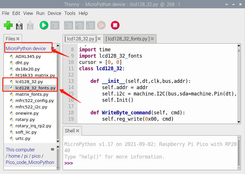
Then we find LCD 128*32.py in the code path we saved, then double-click to open the code, and then click to run the code.
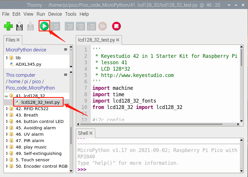
Test Code
'''
 * Keyestudio 42 in 1 Starter Kit for Raspberry Pi Pico
 * lesson 41
 * LCD 128*32
 * http://www.keyestudio.com
'''
import machine
import time
import lcd128_32_fonts
from lcd128_32 import lcd128_32

#i2c config
clock_pin = 21
data_pin = 20
bus = 0
i2c_addr = 0x3f
use_i2c = True

def scan_for_devices():
    i2c = machine.I2C(bus,sda=machine.Pin(data_pin),scl=machine.Pin(clock_pin))
    devices = i2c.scan()
    if devices:
        for d in devices:
            print(hex(d))
    else:
        print('no i2c devices')

if use_i2c:
    scan_for_devices()
    lcd = lcd128_32(data_pin, clock_pin, bus, i2c_addr)


lcd.Clear()

lcd.Cursor(0, 7)
lcd.Display("KEYES")
lcd.Cursor(1, 0)
lcd.Display("ABCDEFGHIJKLMNOPQR")
lcd.Cursor(2, 0)
lcd.Display("123456789+-*/<>=$@")
lcd.Cursor(3, 0)
lcd.Display("%^&(){}:;'|?,.~\\[]")

while True:
    scan_for_devices()
    time.sleep(0.5)
Code Explanation
Import the library:
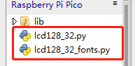
scan_for_devices(): This function is an IIC addressing function; if an IIC device is identified, the IIC address of the device is printed, as shown in the figure:
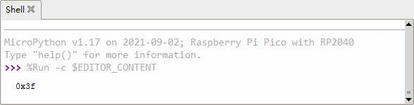
If the device is not recognized, no i2c devices will be printed out and then report an error, as shown in the figure:
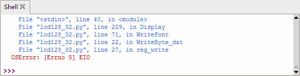
lcd.Cursor(0, 7): The function to set cursor , that is, set the position where the character is displayed on the lcd, the first parameter is the parameter of the row, the second is the parameter of the column
lcd.Display(“KEYES”): Display character content, here “KEYES” is displayed.
Test Result
Wire up and upload the test code, the 128X32LCD module will show KEYES on the first line, ABCDEFGHIJKLMNOPQR on the second line, 123456789+-*/<>=$@ on the third line and “%^&(){}:;’|?,.~\[]” on the fourth line, as shown below.
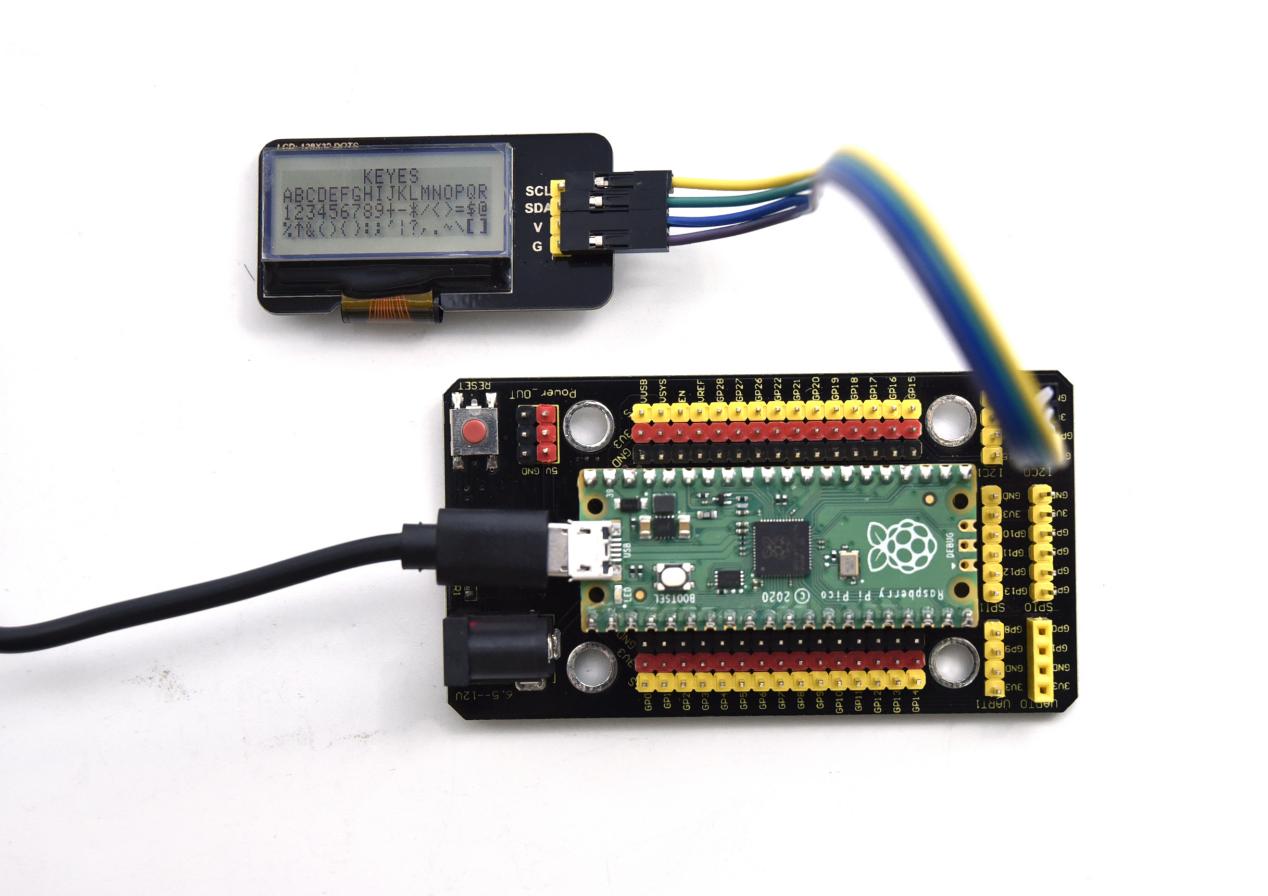
Project 42: RFID Module

Description
RFIDRFID-RC522 radio frequency module adopts a Philips MFRC522 original chip to design card reading circuit, easy to use and low cost, suitable for equipment development and card reader development and so on.
RFID or Radio Frequency Identification system consists of two main components, a transponder/tag attached to an object to be identified, and a Transceiver also known as interrogator/Reader.
In the experiment, the data read by the card swipe module is 4 hexadecimal numbers, and we print these four hexadecimal numbers as strings. For example, we read the data of the IC card below: 0x8d, 0xfe, 0x6c, 0x4d, and the information string displayed in the shell is 8dfe6c4d; the data read from the keychain is: 0xbc, 0x33, 0x76, 0x6e, and the information is displayed in the shell The string is bc33766e.
Working Principle
RFID (Radio Frequency Identification)
Radio frequency identification, the card reader is composed of a radio frequency module and a high-level magnetic field. The Tag transponder is a sensing device, and this device does not contain a battery. It only contains tiny integrated circuit chips and media for storing data and antennas for receiving and transmitting signals. To read the data in the tag, first put it into the reading range of the card reader. The reader will generate a magnetic field, and because the magnetic energy generates electricity according to Lenz’s law, the RFID tag will supply power, thereby activating the device.
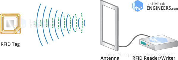
Required Components
|
|
|
|
|---|---|---|---|
Raspberry Pi Pico Board*1 |
Raspberry Pi Pico Expansion Board*1 |
Keyestudio DIY RFID Module*1 |
4P Dupont Wire*1 |
|
|
|
|
Micro USB Cable*1 |
Key*1 |
IC Card*1 |


Connection Diagram
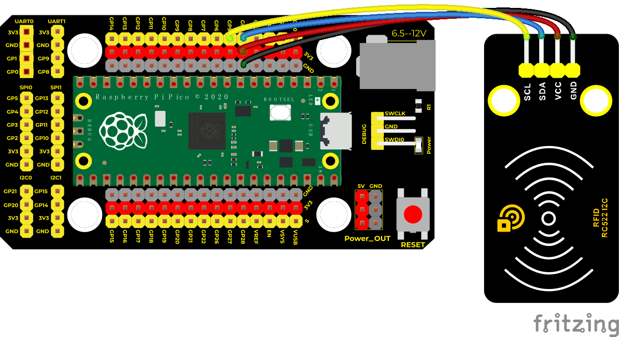
Run the test code
Find and double-click mfrc522.py and click
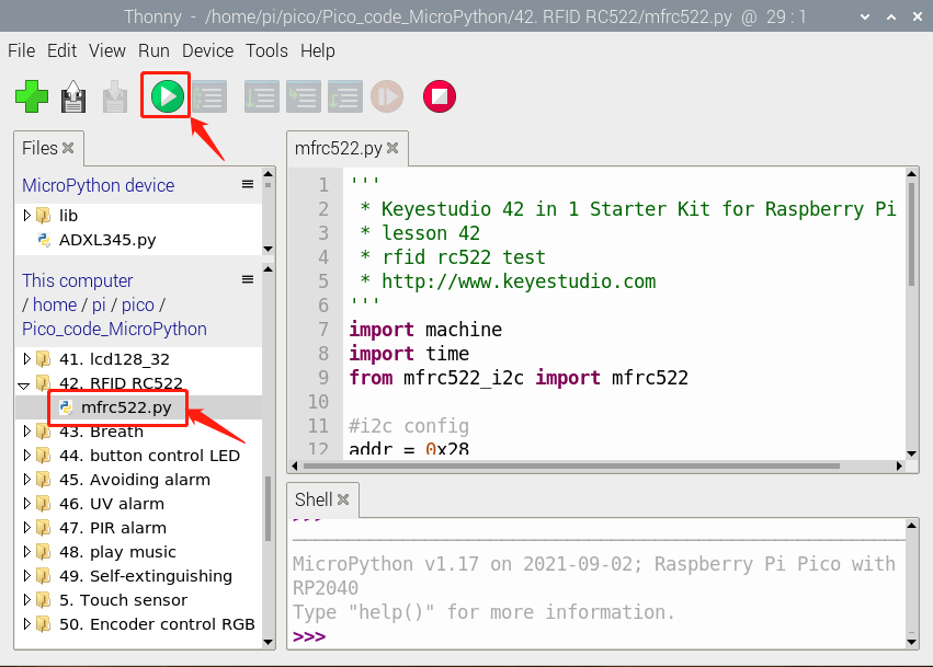
Before running the code, we save the following code to pico, import the module, and name it mfrc522_config.py: (also in the library file folder we provide)
class Uid:
    size    = 0                  # Number of bytes in the UID. 4, 7 or 10.
    uidByte = [0,0,0,0,0,0,0,0,0,0]
    sak     = 0                  # The SAK (Select acknowledge) byte returned from the PICC after successful selection.


class mfrc522Config(Uid):
    # MFRC522 registers. Described in chapter 9 of the datasheet.
    # PCD_Register
    # Page 0: Command and status
    #                 0x00 #reserved for future use
    CommandReg      = 0x01 #starts and stops command execution
    ComIEnReg       = 0x02 #enable and disable interrupt request control bits
    DivIEnReg       = 0x03 #enable and disable interrupt request control bits
    ComIrqReg       = 0x04 #interrupt request bits
    DivIrqReg       = 0x05 #interrupt request bits
    ErrorReg        = 0x06 #error bits showing the error status of the last command executed
    Status1Reg      = 0x07 #communication status bits
    Status2Reg      = 0x08 #receiver and transmitter status bits
    FIFODataReg     = 0x09 #input and output of 64 byte FIFO buffer
    FIFOLevelReg    = 0x0A #number of bytes stored in the FIFO buffer
    WaterLevelReg   = 0x0B #level for FIFO underflow and overflow warning
    ControlReg      = 0x0C #miscellaneous control registers
    BitFramingReg   = 0x0D #adjustments for bit-oriented frames
    CollReg         = 0x0E #bit position of the first bit-collision detected on the RF interface
    #                 0x0F #reserved for future use

    # Page 1: Command
    #                 0x10 #reserved for future use
    ModeReg         = 0x11 #defines general modes for transmitting and receiving
    TxModeReg       = 0x12 #defines transmission data rate and framing
    RxModeReg       = 0x13 #defines reception data rate and framing
    TxControlReg    = 0x14 #controls the logical behavior of the antenna driver pins TX1 and TX2
    TxASKReg        = 0x15 #controls the setting of the transmission modulation
    TxSelReg        = 0x16 #elects the internal sources for the antenna driver
    RxSelReg        = 0x17 #selects internal receiver settings
    RxThresholdReg  = 0x18 #selects thresholds for the bit decoder
    DemodReg        = 0x19 #defines demodulator settings
    #                 0x1A #reserved for future use
    #                 0x1B #eserved for future use
    MfTxReg         = 0x1C #controls some MIFARE communication transmit parameters
    MfRxReg         = 0x1D #controls some MIFARE communication receive parameters
    #                 0x1E #reserved for future use
    SerialSpeedReg  = 0x1F #selects the speed of the serial UART interface

    # Page 2: Configuration
    #   0x20 reserved for future use
    CRCResultRegH   = 0x21 #shows the MSB and LSB values of the CRC calculation
    CRCResultRegL   = 0x22 #
    #                 0x23 #reserved for future use
    ModWidthReg     = 0x24 #controls the ModWidth setting?
    #                 0x25 #reserved for future use
    RFCfgReg        = 0x26 #onfigures the receiver gain
    GsNReg          = 0x27 #selects the conductance of the antenna driver pins TX1 and TX2 for modulation
    CWGsPReg        = 0x28 #defines the conductance of the p-driver output during periods of no modulation
    ModGsPReg       = 0x29 #defines the conductance of the p-driver output during periods of modulation
    TModeReg        = 0x2A #defines settings for the internal timer
    TPrescalerReg   = 0x2B #the lower 8 bits of the TPrescaler value. The 4 high bits are in TModeReg.
    TReloadRegH     = 0x2C #efines the 16-bit timer reload value
    TReloadRegL     = 0x2D #
    TCounterValueRegH   = 0x2E #shows the 16-bit timer value
    TCounterValueRegL   = 0x2F #

    # Page 3: Test Registers
    #                 0x30 #reserved for future use
    TestSel1Reg     = 0x31 #general test signal configuration
    TestSel2Reg     = 0x32 #eneral test signal configuration
    TestPinEnReg    = 0x33 #enables pin output driver on pins D1 to D7
    TestPinValueReg = 0x34 #defines the values for D1 to D7 when it is used as an I/O bus
    TestBusReg      = 0x35 #shows the status of the internal test bus
    AutoTestReg     = 0x36 #controls the digital self test
    VersionReg      = 0x37 #shows the software version
    AnalogTestReg   = 0x38 #controls the pins AUX1 and AUX2
    TestDAC1Reg     = 0x39 #defines the test value for TestDAC1
    TestDAC2Reg     = 0x3A #defines the test value for TestDAC2
    TestADCReg      = 0x3B #shows the value of ADC I and Q channels
    #                 0x3C #reserved for production tests
    #                 0x3D #reserved for production tests
    #                 0x3E #reserved for production tests
    #                 0x3F #reserved for production tests

    # MFRC522 commands. Described in chapter 10 of the datasheet.
    # PCD_Command
    PCD_Idle             = 0x00 #no action, cancels current command execution
    PCD_Mem              = 0x01 #stores 25 bytes into the internal buffer
    PCD_GenerateRandomID = 0x02 #generates a 10-byte random ID number
    PCD_CalcCRC          = 0x03 #activates the CRC coprocessor or performs a self test
    PCD_Transmit         = 0x04 #transmits data from the FIFO buffer
    PCD_NoCmdChange      = 0x07 #no command change, can be used to modify the CommandReg register bits without affecting the command, for example, the PowerDown bit
    PCD_Receive          = 0x08 #activates the receiver circuits
    PCD_Transceive       = 0x0C #transmits data from FIFO buffer to antenna and automatically activates the receiver after transmission
    PCD_MFAuthent        = 0x0E #performs the MIFARE standard authentication as a reader
    PCD_SoftReset        = 0x0F #resets the MFRC522

    # MFRC522 RxGain[2:0] masks, defines the receiver's signal voltage gain factor (on the PCD).
    # Described in 9.3.3.6 / table 98 of the datasheet at http://www.nxp.com/documents/data_sheet/MFRC522.pdf
    # PCD_RxGain
    RxGain_18dB          = 0x00 << 4 #000b - 18 dB, minimum
    RxGain_23dB          = 0x01 << 4 #001b - 23 dB
    RxGain_18dB_2        = 0x02 << 4 #010b - 18 dB, it seems 010b is a duplicate for 000b
    RxGain_23dB_2        = 0x03 << 4 #011b - 23 dB, it seems 011b is a duplicate for 001b
    RxGain_33dB          = 0x04 << 4 #100b - 33 dB, average, and typical default
    RxGain_38dB          = 0x05 << 4 #101b - 38 dB
    RxGain_43dB          = 0x06 << 4 #110b - 43 dB
    RxGain_48dB          = 0x07 << 4 #111b - 48 dB, maximum
    RxGain_min           = 0x00 << 4 #000b - 18 dB, minimum, convenience for RxGain_18dB
    RxGain_avg           = 0x04 << 4 #100b - 33 dB, average, convenience for RxGain_33dB
    RxGain_max           = 0x07 << 4 #111b - 48 dB, maximum, convenience for RxGain_48dB

    # Commands sent to the PICC.
    # The commands used by the PCD to manage communication with several PICCs (ISO 14443-3, Type A, section 6.4)
    PICC_CMD_REQA           = 0x26 #REQuest command, Type A. Invites PICCs in state IDLE to go to READY and prepare for anticollision or selection. 7 bit frame.
    PICC_CMD_WUPA           = 0x52 #Wake-UP command, Type A. Invites PICCs in state IDLE and HALT to go to READY(*) and prepare for anticollision or selection. 7 bit frame.
    PICC_CMD_CT             = 0x88 #Cascade Tag. Not really a command, but used during anti collision.
    PICC_CMD_SEL_CL1        = 0x93 #Anti collision/Select, Cascade Level 1
    PICC_CMD_SEL_CL2        = 0x95 #Anti collision/Select, Cascade Level 2
    PICC_CMD_SEL_CL3        = 0x97 #Anti collision/Select, Cascade Level 3
    PICC_CMD_HLTA           = 0x50 #HaLT command, Type A. Instructs an ACTIVE PICC to go to state HALT.
    # The commands used for MIFARE Classic (from http://www.nxp.com/documents/data_sheet/MF1S503x.pdf, Section 9)
    # Use PCD_MFAuthent to authenticate access to a sector, then use these commands to read/write/modify the blocks on the sector.
    # The read/write commands can also be used for MIFARE Ultralight.
    PICC_CMD_MF_AUTH_KEY_A  = 0x60 #Perform authentication with Key A
    PICC_CMD_MF_AUTH_KEY_B  = 0x61 #Perform authentication with Key B
    PICC_CMD_MF_READ        = 0x30 #Reads one 16 byte block from the authenticated sector of the PICC. Also used for MIFARE Ultralight.
    PICC_CMD_MF_WRITE       = 0xA0 #Writes one 16 byte block to the authenticated sector of the PICC. Called "COMPATIBILITY WRITE" for MIFARE Ultralight.
    PICC_CMD_MF_DECREMENT   = 0xC0 #Decrements the contents of a block and stores the result in the internal data register.
    PICC_CMD_MF_INCREMENT   = 0xC1 #Increments the contents of a block and stores the result in the internal data register.
    PICC_CMD_MF_RESTORE     = 0xC2 #Reads the contents of a block into the internal data register.
    PICC_CMD_MF_TRANSFER    = 0xB0 #Writes the contents of the internal data register to a block.
    # The commands used for MIFARE Ultralight (from http://www.nxp.com/documents/data_sheet/MF0ICU1.pdf, Section 8.6)
    # The PICC_CMD_MF_READ and PICC_CMD_MF_WRITE can also be used for MIFARE Ultralight.
    PICC_CMD_UL_WRITE       = 0xA2 #Writes one 4 byte page to the PICC.

    # MIFARE constants that does not fit anywhere else
    #  MIFARE_Misc
    MF_ACK                  = 0xA #The MIFARE Classic uses a 4 bit ACK/NAK. Any other value than 0xA is NAK.
    MF_KEY_SIZE             = 6   #A Mifare Crypto1 key is 6 bytes.

    # PICC types we can detect. Remember to update PICC_GetTypeName() if you add more.
    # PICC_Type
    PICC_TYPE_UNKNOWN       = 0
    PICC_TYPE_ISO_14443_4   = 1 #PICC compliant with ISO/IEC 14443-4
    PICC_TYPE_ISO_18092     = 2 #PICC compliant with ISO/IEC 18092 (NFC)
    PICC_TYPE_MIFARE_MINI   = 3 #MIFARE Classic protocol, 320 bytes
    PICC_TYPE_MIFARE_1K     = 4 #MIFARE Classic protocol, 1KB
    PICC_TYPE_MIFARE_4K     = 5 #MIFARE Classic protocol, 4KB
    PICC_TYPE_MIFARE_UL     = 6 #MIFARE Ultralight or Ultralight C
    PICC_TYPE_MIFARE_PLUS   = 7 #MIFARE Plus
    PICC_TYPE_TNP3XXX       = 8 #Only mentioned in NXP AN 10833 MIFARE Type Identification Procedure
    ICC_TYPE_NOT_COMPLETE   = 255 #SAK indicates UID is not complete.

    # Return codes from the functions in this class. Remember to update GetStatusCodeName() if you add more.
    # StatusCode
    STATUS_OK               = 1 #Success
    STATUS_ERROR            = 2 #Error in communication
    STATUS_COLLISION        = 3 #Collission detected
    STATUS_TIMEOUT          = 4 #Timeout in communication.
    STATUS_NO_ROOM          = 5 #A buffer is not big enough.
    STATUS_INTERNAL_ERROR   = 6 #Internal error in the code. Should not happen ;-)
    STATUS_INVALID          = 7 #Invalid argument.
    STATUS_CRC_WRONG        = 8 #The CRC_A does not match
    STATUS_MIFARE_NACK      = 9 #A MIFARE PICC responded with NAK.

    # Size of the MFRC522 FIFO
    FIFO_SIZE               = 64 #The FIFO is 64 bytes.

    uid = Uid
Then save the following code to pico and name it soft_iic.py:
from machine import Pin
import time

class softIIC:

    def __init__(self, scl_, sda_, addr_):
        self.addr = addr_
        self.scl  = scl_
        self.sda  = sda_


    def IIC_start(self):
        Pin_scl = Pin(self.scl, Pin.OUT, value=1)    # create output pin
        Pin_sda = Pin(self.sda, Pin.OUT, value=1)    # create output pin
        #Pin_sda.value(1)
        #Pin_scl.value(1)
        time.sleep_us(5)
        #time.sleep(1)
        Pin_sda.value(0)
        time.sleep_us(5)
        Pin_scl.value(0)
        #time.sleep(1)


    def IIC_stop(self):
        Pin_scl = Pin(self.scl, Pin.OUT, value=0)    # create output pin
        Pin_sda = Pin(self.sda, Pin.OUT, value=0)    # create output pin
        #Pin_scl.value(0)
        #Pin_sda.value(0)
        time.sleep_us(5)
        Pin_scl.value(1)
        Pin_sda.value(1)
        time.sleep_us(5)


    def IIC_master_ack(self):
        Pin_scl = Pin(self.scl, Pin.OUT, value=0)    # create output pin
        Pin_sda = Pin(self.sda, Pin.OUT, value=0)    # create output pin
        #Pin_scl.value(0)
        #Pin_sda.value(0)
        time.sleep_us(5)

        Pin_scl.value(1)
        time.sleep_us(5)
        Pin_scl.value(0)
        #Pin_sda.value(1)


    def IIC_master_notack(self):
        Pin_scl = Pin(self.scl, Pin.OUT, value=0)    # create output pin
        Pin_sda = Pin(self.sda, Pin.OUT, value=1)    # create output pin
        #Pin_scl.value(0)
        #Pin_sda.value(1)
        time.sleep_us(5)
        Pin_scl.value(1)
        time.sleep_us(5)
        Pin_scl.value(0)


    def IIC_slave_ack(self):
        i=0
        Pin_scl = Pin(self.scl, Pin.OUT, value=0)    # create output pin
        Pin_sda = Pin(self.sda, Pin.IN, Pin.PULL_UP)     # create input pin
        Pin_scl.value(1)
        time.sleep_us(5)
        while Pin_sda.value() == 1:
            time.sleep_us(1)
            i = i+1
            if i>20:
                while 1 :
                    print("IIC slave device not ack")
                    time.sleep(1)
                #return


    def IIC_read_byte(self):
        dat = 0
        Pin_scl = Pin(self.scl, Pin.OUT, value=0)    # create input pin
        Pin_sda = Pin(self.sda, Pin.IN, Pin.PULL_UP)     # create input pin
        for i in range(8):
            Pin_scl.value(0)
            time.sleep_us(3)
            Pin_scl.value(1)
            time.sleep_us(2)
            #print(Pin_sda.value())
            if Pin_sda.value() == 1:
                dat = dat<<1 | 1
            else:
                dat = dat<<1
            time.sleep_us(5)
        return dat


    def IIC_write_byte(self, dat):
        Pin_scl = Pin(self.scl, Pin.OUT, value=0)    # create output pin
        Pin_sda = Pin(self.sda, Pin.OUT, value=0)    # create output pin
        for i in range(8):
            if 0x80 & dat == 0x80:
                Pin_sda.value(1)
                #print(1)
            else:
                Pin_sda.value(0)
                #print(0)
            Pin_scl.value(1)
            time.sleep_us(5)
            Pin_scl.value(0)
            time.sleep_us(5)
            dat = dat<<1
        #print("--------------------")


    def Read(self, _adr, _reg):
        self.IIC_start()
        self.IIC_write_byte(_adr<<1)
        self.IIC_slave_ack()
        #print("--------------1")
        self.IIC_write_byte(_reg)
        self.IIC_slave_ack()
        self.IIC_stop()
        #print("--------------2")
        self.IIC_start()
        self.IIC_write_byte((_adr<<1)|1)
        self.IIC_slave_ack()
        #print("--------------3")
        dat = self.IIC_read_byte()
        self.IIC_master_notack()
        self.IIC_stop()
        return dat


    def Write(self, _adr, _reg, _dat):
        self.IIC_start()
        self.IIC_write_byte(_adr<<1)
        self.IIC_slave_ack()

        self.IIC_write_byte(_reg)
        self.IIC_slave_ack()

        self.IIC_write_byte(_dat)
        self.IIC_slave_ack()
        self.IIC_stop()
Then save the following code to pico and name it mfrc522_i2c.py
from machine import Pin
import time
from mfrc522_config import mfrc522Config
from soft_iic import softIIC
class mfrc522(mfrc522Config,softIIC):
def __init__(self, scl_, sda_, addr_):
# Invoke the parent class's constructor
softIIC.__init__(self, scl_, sda_, addr_)
# Writes a byte to the specified register in the MFRC522 chip.
# The interface is described in the datasheet section 8.1.2.
def PCD_WriteRegister(self,
_reg, #The register to write to. One of the PCD_Register enums.
_dat #The value to write.
):
self.Write(self.addr, _reg, _dat)
# Writes a number of bytes to the specified register in the MFRC522 chip.
# The interface is described in the datasheet section 8.1.2.
def PCD_WriteRegister_(self,
reg, #The register to write to. One of the PCD_Register enums.
count, #The number of bytes to write to the register
lst #The values to write. Byte array.
):
self.IIC_start()
self.IIC_write_byte(self.addr<<1)
self.IIC_slave_ack()
self.IIC_write_byte(reg)
self.IIC_slave_ack()
for i in range(count):
self.IIC_write_byte(lst[i])
self.IIC_slave_ack()
self.IIC_stop()
# Reads a byte from the specified register in the MFRC522 chip.
# The interface is described in the datasheet section 8.1.2.
def PCD_ReadRegister(self, _reg): # The register to read from. One of the PCD_Register enums.
return self.Read(self.addr,_reg)
# End PCD_ReadRegister()
# Reads a number of bytes from the specified register in the MFRC522 chip.
# The interface is described in the datasheet section 8.1.2.
# self.PCD_ReadRegister_(self.FIFODataReg, n, backData, rxAlign)
def PCD_ReadRegister_(self,
reg, # The register to read from. One of the PCD_Register enums.
count, # The number of bytes to read
values, # Byte array to store the values in.
rxAlign = 0 # Only bit positions rxAlign..7 in values[0] are updated.
):
if count == 0:
return
self.IIC_start()
self.IIC_write_byte(self.addr<<1)
self.IIC_slave_ack()
#print("--------------1")
self.IIC_write_byte(reg)
self.IIC_slave_ack()
self.IIC_stop()
#print("--------------2")
self.IIC_start()
self.IIC_write_byte((self.addr<<1)|1)
self.IIC_slave_ack()
#print("--------------3")
for i in range(count):
if i == 0 and rxAlign != 0: # Only update bit positions rxAlign..7 in values[0]
# Create bit mask for bit positions rxAlign..7
mask = 0
for i in range(rxAlign, 8):
mask |= (1<<i)
# Read value and tell that we want to read the same address again.
value = self.IIC_read_byte()
# Apply mask to both current value of values[0] and the new data in value.
values[0] = (values[i] & ~mask) | (value & mask)
else: # Normal case
values[i] = self.IIC_read_byte()
if i < count - 1:
self.IIC_master_ack()
else:
self.IIC_master_notack()
self.IIC_stop()
#print(values)
# End PCD_ReadRegister()
def PCD_Init(self):
self.PCD_Reset()
# When communicating with a PICC we need a timeout if something goes wrong.
# f_timer = 13.56 MHz / (2*TPreScaler+1) where TPreScaler = [TPrescaler_Hi:TPrescaler_Lo].
# TPrescaler_Hi are the four low bits in TModeReg. TPrescaler_Lo is TPrescalerReg.
self.PCD_WriteRegister(self.TModeReg, 0x80) # TAuto=1; timer starts automatically at the end of the transmission in all communication modes at all speeds
self.PCD_WriteRegister(self.TPrescalerReg, 0xA9) # TPreScaler = TModeReg[3..0]:TPrescalerReg, ie 0x0A9 = 169 => f_timer=40kHz, ie a timer period of 25�s.
self.PCD_WriteRegister(self.TReloadRegH, 0x03) # Reload timer with 0x3E8 = 1000, ie 25ms before timeout.
self.PCD_WriteRegister(self.TReloadRegL, 0xE8)
self.PCD_WriteRegister(self.TxASKReg, 0x40) # Default 0x00. Force a 100 % ASK modulation independent of the ModGsPReg register setting
self.PCD_WriteRegister(self.ModeReg, 0x3D) # Default 0x3F. Set the preset value for the CRC coprocessor for the CalcCRC command to 0x6363 (ISO 14443-3 part 6.2.4)
self.PCD_AntennaOn() # Enable the antenna driver pins TX1 and TX2 (they were disabled by the reset)
# End PCD_Init()
# Performs a soft reset on the MFRC522 chip and waits for it to be ready again.
def PCD_Reset(self):
# Issue the SoftReset command.
self.PCD_WriteRegister(self.CommandReg, self.PCD_SoftReset)
time.sleep(1)
if self.PCD_ReadRegister(self.CommandReg) & (1<<4):
print("Reset error!")
# Turns the antenna on by enabling pins TX1 and TX2.
# After a reset these pins are disabled.
def PCD_AntennaOn(self):
value = self.PCD_ReadRegister(self.TxControlReg)
#print("AntennaOn data:" + str(value))
if value & 0x03 != 0x03:
self.PCD_WriteRegister(self.TxControlReg, value | 0x03)
#End PCD_AntennaOn()
# Turns the antenna off by disabling pins TX1 and TX2.
def PCD_AntennaOff(self):
self.PCD_ClearRegisterBitMask(self.TxControlReg, 0x03)
# Sets the bits given in mask in register reg.
def PCD_SetRegisterBitMask(self,
reg, # The register to update. One of the PCD_Register enums.
mask # The bits to set.
):
tmp = self.PCD_ReadRegister(reg)
self.PCD_WriteRegister(reg, tmp | mask) # set bit mask
# End PCD_SetRegisterBitMask()
# Clears the bits given in mask from register reg.
def PCD_ClearRegisterBitMask(self,
reg, # The register to update. One of the PCD_Register enums.
mask # The bits to clear.
):
tmp = self.PCD_ReadRegister(reg)
self.PCD_WriteRegister(reg, tmp & (~mask)) #clear bit mask
# End PCD_ClearRegisterBitMask()
# Use the CRC coprocessor in the MFRC522 to calculate a CRC_A.
#
# @return STATUS_OK on success, STATUS_??? otherwise.
def PCD_CalculateCRC(self,
data, #In: Pointer to the data to transfer to the FIFO for CRC calculation.
length, #In: The number of bytes to transfer.
result #Out: Pointer to result buffer. Result is written to result[0..1], low byte first.
):
self.PCD_WriteRegister(self.CommandReg, self.PCD_Idle) # Stop any active command.
self.PCD_WriteRegister(self.DivIrqReg, 0x04) # Clear the CRCIRq interrupt request bit
self.PCD_SetRegisterBitMask(self.FIFOLevelReg, 0x80) # FlushBuffer = 1, FIFO initialization
self.PCD_WriteRegister_(self.FIFODataReg, length, data) # Write data to the FIFO
self.PCD_WriteRegister(self.CommandReg, self.PCD_CalcCRC) # Start the calculation
# Wait for the CRC calculation to complete. Each iteration of the while-loop takes 17.73�s.
while True:
n = self.PCD_ReadRegister(self.DivIrqReg) # DivIrqReg[7..0] bits are: Set2 reserved reserved MfinActIRq reserved CRCIRq reserved reserved
if (n & 0x04): # CRCIRq bit set - calculation done
break
if (--i == 0): # The emergency break. We will eventually terminate on this one after 89ms. Communication with the MFRC522 might be down.
return self.STATUS_TIMEOUT
self.PCD_WriteRegister(self.CommandReg, self.PCD_Idle) # Stop calculating CRC for new content in the FIFO.
# Transfer the result from the registers to the result buffer
result[0] = self.PCD_ReadRegister(self.CRCResultRegL)
result[1] = self.PCD_ReadRegister(self.CRCResultRegH)
return self.STATUS_OK
# End PCD_CalculateCRC()
# Executes the Transceive command.
# CRC validation can only be done if backData and backLen are specified.
#
# @return STATUS_OK on success, STATUS_??? otherwise.
def PCD_TransceiveData(self,
sendData, # Pointer to the data to transfer to the FIFO.
sendLen, # Number of bytes to transfer to the FIFO.
backData, # NULL or pointer to buffer if data should be read back after executing the command.
backLen, # In: Max number of bytes to write to *backData. Out: The number of bytes returned.
validBits, # In/Out: The number of valid bits in the last byte. 0 for 8 valid bits. Default NULL.
rxAlign, # In: Defines the bit position in backData[0] for the first bit received. Default 0.
checkCRC # In: True => The last two bytes of the response is assumed to be a CRC_A that must be validated.
):
waitIRq = 0x30
return self.PCD_CommunicateWithPICC(self.PCD_Transceive, waitIRq, sendData, sendLen, backData, backLen, validBits, rxAlign, checkCRC)
# End PCD_TransceiveData()
# Transfers data to the MFRC522 FIFO, executes a command, waits for completion and transfers data back from the FIFO.
# CRC validation can only be done if backData and backLen are specified.
#
# @return STATUS_OK on success, STATUS_??? otherwise.
# result = self.PCD_TransceiveData(buffer, bufferUsed, responseBuffer, responseLength, tLB, rxAlign, 0)
def PCD_CommunicateWithPICC(self,
command, # The command to execute. One of the PCD_Command enums.
waitIRq, # The bits in the ComIrqReg register that signals successful completion of the command.
sendData, # Pointer to the data to transfer to the FIFO.
sendLen, # Number of bytes to transfer to the FIFO.
backData, # NULL or pointer to buffer if data should be read back after executing the command.
backLen, # In: Max number of bytes to write to *backData. Out: The number of bytes returned.
validBits, # In/Out: The number of valid bits in the last byte. 0 for 8 valid bits.
rxAlign, # In: Defines the bit position in backData[0] for the first bit received. Default 0.
checkCRC # In: True => The last two bytes of the response is assumed to be a CRC_A that must be validated.
):
txLastBits = validBits[0] if validBits != None else 0
bitFraming = (rxAlign << 4) + txLastBits # RxAlign = BitFramingReg[6..4]. TxLastBits = BitFramingReg[2..0]
self.PCD_WriteRegister(self.CommandReg, self.PCD_Idle) # Stop any active command.
self.PCD_WriteRegister(self.ComIrqReg, 0x7F) # Clear all seven interrupt request bits
self.PCD_SetRegisterBitMask(self.FIFOLevelReg, 0x80) # FlushBuffer = 1, FIFO initialization
self.PCD_WriteRegister_(self.FIFODataReg, sendLen, sendData) # Write sendData to the FIFO
self.PCD_WriteRegister(self.BitFramingReg, bitFraming) # Bit adjustments
self.PCD_WriteRegister(self.CommandReg, command) # Execute the command
if command == self.PCD_Transceive:
self.PCD_SetRegisterBitMask(self.BitFramingReg, 0x80) # StartSend=1, transmission of data starts
# Wait for the command to complete.
# In PCD_Init() we set the TAuto flag in TModeReg. This means the timer automatically starts when the PCD stops transmitting.
# Each iteration of the do-while-loop takes 17.86�s.
i = 2000
while True:
n = self.PCD_ReadRegister(self.ComIrqReg) #ComIrqReg[7..0] bits are: Set1 TxIRq RxIRq IdleIRq HiAlertIRq LoAlertIRq ErrIRq TimerIRq
if n & waitIRq:
break
if n & 0x01:
return self.STATUS_TIMEOUT
if --i == 0:
return self.STATUS_TIMEOUT
# Stop now if any errors except collisions were detected.
errorRegValue = self.PCD_ReadRegister(self.ErrorReg) # ErrorReg[7..0] bits are: WrErr TempErr reserved BufferOvfl CollErr CRCErr ParityErr ProtocolErr
if errorRegValue & 0x13: # BufferOvfl ParityErr ProtocolErr
return self.STATUS_ERROR
# If the caller wants data back, get it from the MFRC522.
if backData != None and backLen != None :
n = self.PCD_ReadRegister(self.FIFOLevelReg) # Number of bytes in the FIFO
if n> backLen[0]:
return self.STATUS_NO_ROOM
backLen[0] = n # Number of bytes returned
# Note: Use list mutable types in Python
self.PCD_ReadRegister_(self.FIFODataReg, n, backData, rxAlign) # Get received data from FIFO
#print("backData:")
#print(backData)
_validBits = self.PCD_ReadRegister(self.ControlReg) & 0x07 # RxLastBits[2:0] indicates the number of valid bits in the last received byte. If this value is 000b, the whole byte is valid.
if validBits != None:
validBits[0] = _validBits
# Tell about collisions
if errorRegValue & 0x08: # collErr
return self.STATUS_COLLISION
# Perform CRC_A validation if requested.
if backData != None and backLen != None and checkCRC != 0:
# In this case a MIFARE Classic NAK is not OK.
if backLen[0] == 1 and _validBits[0] == 4:
return self.STATUS_MIFARE_NACK
# We need at least the CRC_A value and all 8 bits of the last byte must be received.
if backLen[0] < 2 or _validBits != 0:
return self.STATUS_CRC_WRONG
# Verify CRC_A - do our own calculation and store the control in controlBuffer.
controlBuffer = [0, 0]
n = self.PCD_CalculateCRC(backData[0], backLen[0] - 2, controlBuffer[0])
if n != self.STATUS_OK:
return n
if (backData[backLen[0] - 2] != controlBuffer[0]) or (backData[backLen[0] - 1] != controlBuffer[1]):
return self.STATUS_CRC_WRONG
return self.STATUS_OK;
# End PCD_CommunicateWithPICC()
# Transmits a REQuest command, Type A. Invites PICCs in state IDLE to go to READY and prepare for anticollision or selection. 7 bit frame.
# Beware: When two PICCs are in the field at the same time I often get STATUS_TIMEOUT - probably due do bad antenna design.
#
# @return STATUS_OK on success, STATUS_??? otherwise.
def PICC_RequestA(self,
bufferATQA, # The buffer to store the ATQA (Answer to request) in
bufferSize # Buffer size, at least two bytes. Also number of bytes returned if STATUS_OK.
):
cmd = [self.PICC_CMD_REQA]
return self.PICC_REQA_or_WUPA(cmd, bufferATQA, bufferSize)
# End PICC_RequestA()
# Transmits REQA or WUPA commands.
# Beware: When two PICCs are in the field at the same time I often get STATUS_TIMEOUT - probably due do bad antenna design.
#
# @return STATUS_OK on success, STATUS_??? otherwise.
def PICC_REQA_or_WUPA(self,
command, # The command to send - PICC_CMD_REQA or PICC_CMD_WUPA
bufferATQA, # The buffer to store the ATQA (Answer to request) in
bufferSize # Buffer size, at least two bytes. Also number of bytes returned if STATUS_OK.
):
if bufferATQA == None or bufferSize[0] < 2: # The ATQA response is 2 bytes long.
return self.STATUS_NO_ROOM
self.PCD_ClearRegisterBitMask(self.CollReg, 0x80) # ValuesAfterColl=1 => Bits received after collision are cleared.
validBits = [7] # For REQA and WUPA we need the short frame format - transmit only 7 bits of the last (and only) byte. TxLastBits = BitFramingReg[2..0]
status = self.PCD_TransceiveData(command, 1, bufferATQA, bufferSize, validBits, 0, 0)
if status != self.STATUS_OK:
return status
if bufferSize[0] != 2 or validBits[0] != 0:
return self.STATUS_ERROR
return self.STATUS_OK
# End PICC_REQA_or_WUPA()
# Transmits SELECT/ANTICOLLISION commands to select a single PICC.
# Before calling this function the PICCs must be placed in the READY(*) state by calling PICC_RequestA() or PICC_WakeupA().
# On success:
# - The chosen PICC is in state ACTIVE(*) and all other PICCs have returned to state IDLE/HALT. (Figure 7 of the ISO/IEC 14443-3 draft.)
# - The UID size and value of the chosen PICC is returned in *uid along with the SAK.
#
# A PICC UID consists of 4, 7 or 10 bytes.
# Only 4 bytes can be specified in a SELECT command, so for the longer UIDs two or three iterations are used:
# UID size Number of UID bytes Cascade levels Example of PICC
# ======== =================== ============== ===============
# single 4 1 MIFARE Classic
# double 7 2 MIFARE Ultralight
# triple 10 3 Not currently in use?
#
# @return STATUS_OK on success, STATUS_??? otherwise.
def PICC_Select(self,
uid, # Pointer to Uid struct. Normally output, but can also be used to supply a known UID.
validBits # The number of known UID bits supplied in *uid. Normally 0. If set you must also supply uid->size.
):
uidComplete = False
selectDone = False
useCascadeTag = False
cascadeLevel = 1
result = 0
count = 0
index = 0
uidIndex = 0 # The first index in uid->uidByte[] that is used in the current Cascade Level.
currentLevelKnownBits = 0 # The number of known UID bits in the current Cascade Level.
buffer = [0,0,0,0,0,0,0,0,0] # The SELECT/ANTICOLLISION commands uses a 7 byte standard frame + 2 bytes CRC_A
bufferUsed = 0 # The number of bytes used in the buffer, ie the number of bytes to transfer to the FIFO.
rxAlign = 0 # Used in BitFramingReg. Defines the bit position for the first bit received.
txLastBits = 0 # Used in BitFramingReg. The number of valid bits in the last transmitted byte.
responseBuffer = [0]
responseLength = [0]
# Description of buffer structure:
# Byte 0: SEL Indicates the Cascade Level: PICC_CMD_SEL_CL1, PICC_CMD_SEL_CL2 or PICC_CMD_SEL_CL3
# Byte 1: NVB Number of Valid Bits (in complete command, not just the UID): High nibble: complete bytes, Low nibble: Extra bits.
# Byte 2: UID-data or CT See explanation below. CT means Cascade Tag.
# Byte 3: UID-data
# Byte 4: UID-data
# Byte 5: UID-data
# Byte 6: BCC Block Check Character - XOR of bytes 2-5
# Byte 7: CRC_A
# Byte 8: CRC_A
# The BCC and CRC_A is only transmitted if we know all the UID bits of the current Cascade Level.
#
# Description of bytes 2-5: (Section 6.5.4 of the ISO/IEC 14443-3 draft: UID contents and cascade levels)
# UID size Cascade level Byte2 Byte3 Byte4 Byte5
# ======== ============= ===== ===== ===== =====
# 4 bytes 1 uid0 uid1 uid2 uid3
# 7 bytes 1 CT uid0 uid1 uid2
# 2 uid3 uid4 uid5 uid6
# 10 bytes 1 CT uid0 uid1 uid2
# 2 CT uid3 uid4 uid5
# 3 uid6 uid7 uid8 uid9
# Sanity checks
if validBits > 80:
return self.STATUS_INVALID
# Prepare MFRC522
self.PCD_ClearRegisterBitMask(self.CollReg, 0x80) # ValuesAfterColl=1 => Bits received after collision are cleared.
# Repeat Cascade Level loop until we have a complete UID.
uidComplete = False
while uidComplete == False:
# Set the Cascade Level in the SEL byte, find out if we need to use the Cascade Tag in byte 2.
if cascadeLevel == 1:
buffer[0] = self.PICC_CMD_SEL_CL1
uidIndex = 0
useCascadeTag = validBits and uid.size > 4 # When we know that the UID has more than 4 bytes
elif cascadeLevel == 2:
buffer[0] = self.PICC_CMD_SEL_CL2
uidIndex = 3
useCascadeTag = validBits and uid.size > 7 # When we know that the UID has more than 7 bytes
elif cascadeLevel == 3:
buffer[0] = self.PICC_CMD_SEL_CL3
uidIndex = 6
useCascadeTag = False # Never used in CL3.
else:
return self.STATUS_INTERNAL_ERROR
# How many UID bits are known in this Cascade Level?
currentLevelKnownBits = validBits - (8 * uidIndex)
if currentLevelKnownBits < 0:
currentLevelKnownBits = 0
# Copy the known bits from uid->uidByte[] to buffer[]
index = 2 # destination index in buffer[]
#print(useCascadeTag);
if useCascadeTag:
index = index+1
buffer[index] = self.PICC_CMD_CT
# The number of bytes needed to represent the known bits for this level.
bytesToCopy = 1 if currentLevelKnownBits % 8 > 0 else 0 # (currentLevelKnownBits % 8 ? 1 : 0)
bytesToCopy = currentLevelKnownBits // 8 + bytesToCopy
if bytesToCopy:
maxBytes = 3 if useCascadeTag else 4 # maxBytes = useCascadeTag ? 3 : 4
if bytesToCopy > maxBytes:
bytesToCopy = maxBytes
for i in range(bytesToCopy):
index = index+1
buffer[index] = uid.uidByte[uidIndex + i]
# Now that the data has been copied we need to include the 8 bits in CT in currentLevelKnownBits
if useCascadeTag:
currentLevelKnownBits = currentLevelKnownBits + 8
# Repeat anti collision loop until we can transmit all UID bits + BCC and receive a SAK - max 32 iterations.
selectDone = False
while selectDone == False:
# Find out how many bits and bytes to send and receive.
if currentLevelKnownBits >= 32: # All UID bits in this Cascade Level are known. This is a SELECT.
# Serial.print(F("SELECT: currentLevelKnownBits=")); Serial.println(currentLevelKnownBits, DEC);
buffer[1] = 0x70 # NVB - Number of Valid Bits: Seven whole bytes
# Calculate BCC - Block Check Character
buffer[6] = buffer[2] ^ buffer[3] ^ buffer[4] ^ buffer[5]
# Calculate CRC_A
tmpBuffer = [buffer[7], buffer[8]]
result = self.PCD_CalculateCRC(buffer, 7, tmpBuffer)
buffer[7] = tmpBuffer[0]
buffer[8] = tmpBuffer[1]
if result != self.STATUS_OK:
return result
txLastBits = 0 # 0 => All 8 bits are valid.
bufferUsed = 9
# Store response in the last 3 bytes of buffer (BCC and CRC_A - not needed after tx)
responseBuffer = [0].copy()
responseBuffer[0] = buffer[6]
responseBuffer = responseBuffer + buffer[7:]
responseLength[0] = 3
bufferFlag = 6
else: # This is an ANTICOLLISION.
# Serial.print(F("ANTICOLLISION: currentLevelKnownBits=")); Serial.println(currentLevelKnownBits, DEC);
txLastBits = currentLevelKnownBits % 8
count = currentLevelKnownBits // 8 # Number of whole bytes in the UID part.
index = 2 + count # Number of whole bytes: SEL + NVB + UIDs
buffer[1] = (index << 4) + txLastBits # NVB - Number of Valid Bits
bufferUsed = 1 if txLastBits else 0
bufferUsed = index + bufferUsed
responseBuffer = [0].copy()
# Store response in the unused part of buffer
responseBuffer[0] = buffer[index]
responseBuffer = responseBuffer + buffer[index+1:]
responseLength[0] = len(buffer) - index
bufferFlag = index
# Set bit adjustments
rxAlign = txLastBits # Having a seperate variable is overkill. But it makes the next line easier to read.
self.PCD_WriteRegister(self.BitFramingReg, (rxAlign << 4) + txLastBits) # RxAlign = BitFramingReg[6..4]. TxLastBits = BitFramingReg[2..0]
#Transmit the buffer and receive the response.
tLB = [txLastBits]
result = self.PCD_TransceiveData(buffer, bufferUsed, responseBuffer, responseLength, tLB, rxAlign, 0)
for i in range(bufferFlag, bufferFlag+responseLength[0]):
buffer[i] = responseBuffer[i-bufferFlag]
if result == self.STATUS_COLLISION: # More than one PICC in the field => collision.
result = self.PCD_ReadRegister(CollReg) # CollReg[7..0] bits are: ValuesAfterColl reserved CollPosNotValid CollPos[4:0]
if result & 0x20:
return self.STATUS_COLLISION # Without a valid collision position we cannot continue
collisionPos = result & 0x1F # Values 0-31, 0 means bit 32.
if collisionPos == 0:
collisionPos = 32
if collisionPos <= currentLevelKnownBits: # No progress - should not happen
return self.STATUS_INTERNAL_ERROR
# Choose the PICC with the bit set.
currentLevelKnownBits = collisionPos
count = (currentLevelKnownBits - 1) % 8 # The bit to modify
index = 1 if count else 0
index = 1 + (currentLevelKnownBits / 8) + index # First byte is index 0.
buffer[index] = buffer[index] | (1 << count)
elif result != self.STATUS_OK:
return result
else: # STATUS_OK
if currentLevelKnownBits >= 32: # This was a SELECT.
selectDone = True # No more anticollision
# We continue below outside the while.
else: # This was an ANTICOLLISION.
# We now have all 32 bits of the UID in this Cascade Level
currentLevelKnownBits = 32
# Run loop again to do the SELECT.
# End of while (!selectDone)
# We do not check the CBB - it was constructed by us above.
# Copy the found UID bytes from buffer[] to uid->uidByte[]
index = 3 if buffer[2] == self.PICC_CMD_CT else 2 # source index in buffer[]
bytesToCopy = 3 if buffer[2] == self.PICC_CMD_CT else 4
for i in range(bytesToCopy):
uid.uidByte[uidIndex + i] = buffer[index]
index = index+1
# Check response SAK (Select Acknowledge)
if responseLength[0] != 3 or txLastBits != 0: # SAK must be exactly 24 bits (1 byte + CRC_A).
return self.STATUS_ERROR
# Verify CRC_A - do our own calculation and store the control in buffer[2..3] - those bytes are not needed anymore.
CRCbuffer = [buffer[2]]
CRCbuffer = CRCbuffer + buffer[3:]
result = self.PCD_CalculateCRC(responseBuffer, 1, CRCbuffer)
buffer[2] = CRCbuffer[0]
buffer[3] = CRCbuffer[1]
if result != self.STATUS_OK:
return result
if (buffer[2] != responseBuffer[1]) or (buffer[3] != responseBuffer[2]):
return self.STATUS_CRC_WRONG
if responseBuffer[0] & 0x04: # Cascade bit set - UID not complete yes
cascadeLevel = cascadeLevel+1
else:
uidComplete = True
uid.sak = responseBuffer[0]
# End of while (!uidComplete)
# Set correct uid->size
uid.size = 3 * cascadeLevel + 1
return self.STATUS_OK
# End PICC_Select()
# Returns true if a PICC responds to PICC_CMD_REQA.
# Only "new" cards in state IDLE are invited. Sleeping cards in state HALT are ignored.
#
# @return bool
def PICC_IsNewCardPresent(self):
bufferATQA = [0, 0]
bufferSize = [len(bufferATQA)]
result = self.PICC_RequestA(bufferATQA, bufferSize)
return result == self.STATUS_OK or result == self.STATUS_COLLISION
# End PICC_IsNewCardPresent()
# Simple wrapper around PICC_Select.
# Returns true if a UID could be read.
# Remember to call PICC_IsNewCardPresent(), PICC_RequestA() or PICC_WakeupA() first.
# The read UID is available in the class variable uid.
#
# @return bool
def PICC_ReadCardSerial(self):
result = self.PICC_Select(self.uid, 0)
return (result == self.STATUS_OK)
# End PICC_ReadCardSerial()
# Show details of PCD - MFRC522 Card Reader details.
def ShowReaderDetails(self):
v = self.PCD_ReadRegister(self.VersionReg)
version = str(v)
if v == 0x91:
version = version + " = v1.0"
elif v == 0x92:
version = version + " = v2.0"
else:
version = version + "unknown"
print("MFRC522 Software Version:" + version)
We can see the modules we saved under mycropython device, that is, in pico
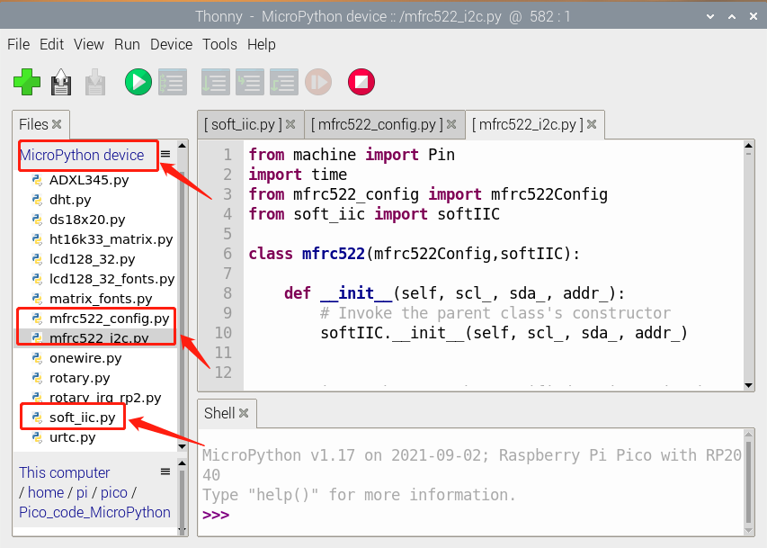
Test Code
'''
 * Keyestudio 42 in 1 Starter Kit for Raspberry Pi Pico
 * lesson 42
 * rfid rc522 test
 * http://www.keyestudio.com
'''
import machine
import time
from mfrc522_i2c import mfrc522

#i2c config
addr = 0x28
scl = 5
sda = 4

rc522 = mfrc522(scl, sda, addr)
rc522.PCD_Init()
rc522.ShowReaderDetails()            # Show details of PCD - MFRC522 Card Reader details

while True:
    if rc522.PICC_IsNewCardPresent():
        #print("Is new card present!")
        if rc522.PICC_ReadCardSerial() == True:
            print("Card UID:")
            print(rc522.uid.uidByte[0 : rc522.uid.size])
    #time.sleep(1)
Code Explanation
First import the module of RFID522:
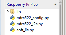
mfrc522_config.py; this is a configuration file that defines some parameters and commands
mfrc522_i2c.py; Initialization and read and write functions
Soft_iic.py; It is the bottom-level read and write function of software I2C. We use the io port to simulate I2C here.
Test Result
When we make the IC card close to the RFID module, the information will be printed out, as shown in the figure below.
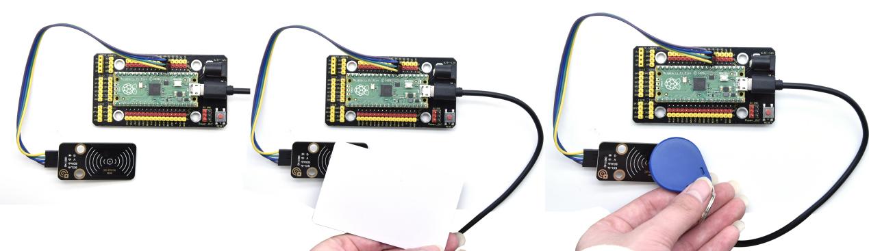
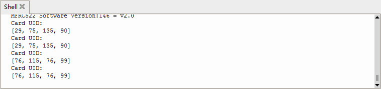
5. Comprehensive Experiments
The previous projects are related to single sensor or module. In the following part, we will combine various sensors and modules to create some comprehensive experiments to perform special functions.
Project 43: Breathing LED

Overview
A “breathing LED” is a phenomenon where an LED’s brightness smoothly changes from dark to bright and back to dark, continuing to do so and giving the illusion of an LED“breathing. This phenomenon is similar to a lung breathing in and out. So how to control LED’s brightness? We need to take advantage of PWM.
Components
|
|
|
|---|---|---|
Raspberry Pi Pico Board*1 |
Raspberry Pi Pico Expansion Board*1 |
Keyestudio White LED Module*1 |
|
|
|
3P Dupont Wire*1 |
Micro USB Cable*1 |
Connection Diagram
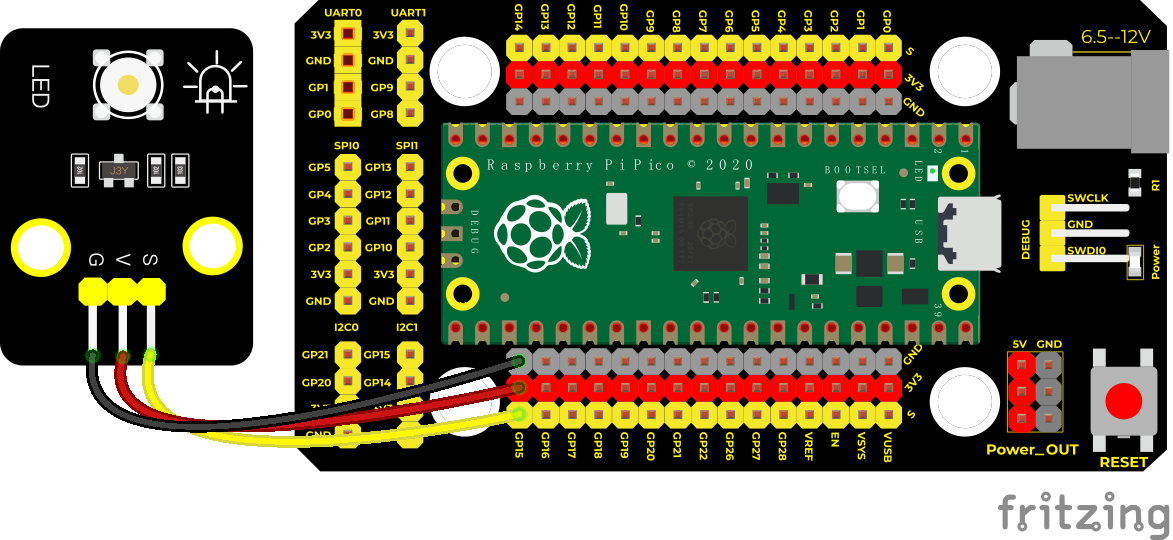
Run the test code
Double-click Breath.py, and clickto run the code.
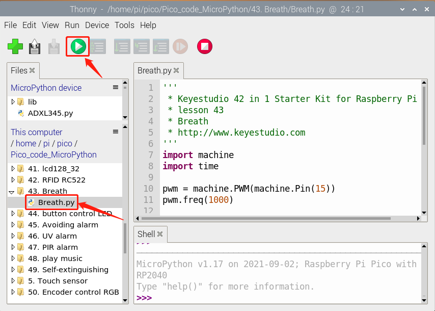
Test Code
'''
 * * Keyestudio 42 in 1 Starter Kit for Raspberry Pi Pico
 * lesson 43
 * Breath
 * http://www.keyestudio.com
'''
import machine
import time

pwm = machine.PWM(machine.Pin(15))
pwm.freq(1000)

duty = 0
direction = 1
while True:
    duty += direction
    if duty > 255:
        duty = 255
        direction = -1
    elif duty < 0:
        duty = 0
        direction = 1
    pwm.duty_u16(duty * duty)
    time.sleep(0.01)
Code Explanation
The larger the set duty cycle, the brighter the LED will be, with a maximum of 65535. The duty increases from 0 to 255 at the beginning, with an increase of 1, and delay in 10 milliseconds for each time, the LED on the module will gradually become brighter.
After PWM is 255*255, i starts to decrease from 255 to 0, decreasing by 1 each time, and delaying 10 milliseconds each time, the LED on the module gradually gets dark. Then it gradually becomes brighter, cycle alternately, just like the human breathes.
We can change the delayed time in the code. There are two ways:
Change the step length or reduce the delayed time.
The step length is supposed to divided by 255, for instance direction = -2 or direction = 2.
Test Result
Run the test code, the LED on the module gradually gets dimmer then brighter, cyclically, like human breathe.
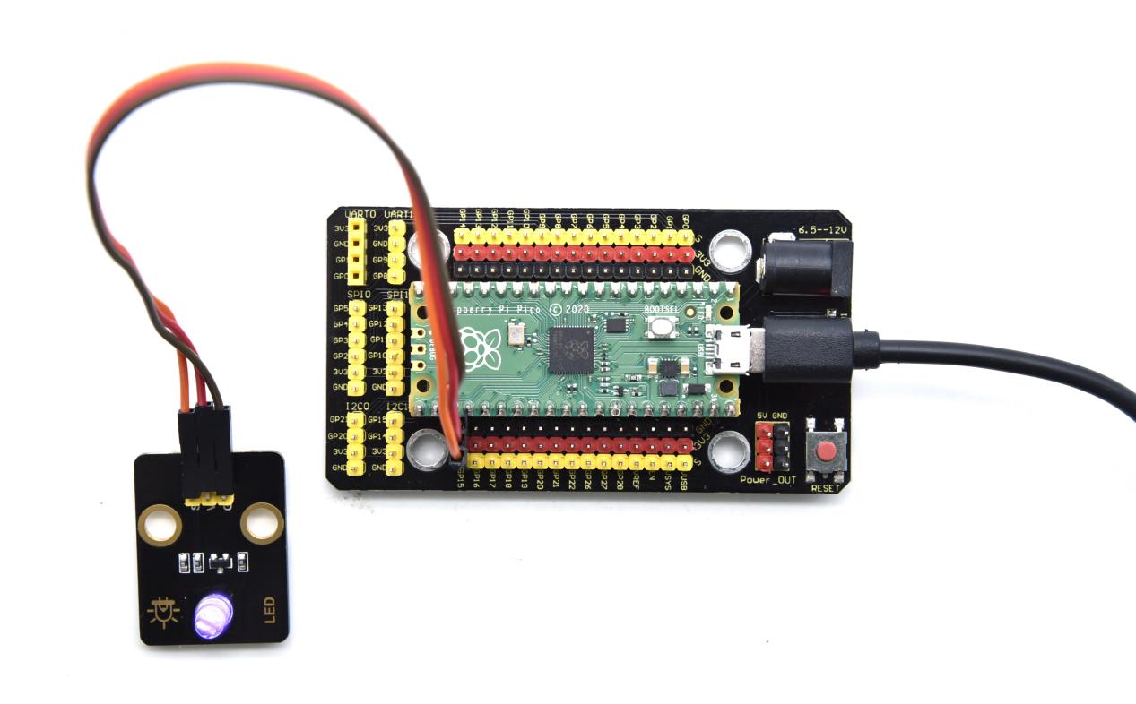
Project 44: Button-controlled LED

Overview
In this lesson, we will make an extension experiment with a button and an LED. When the button is pressed and low levels are output, the LED will light up; when the button is released, the LED will go off. Then we can control a module with another module.
Components
|
|
|
|---|---|---|
Raspberry Pi Pico Board*1 |
Raspberry Pi Pico Expansion Board*1 |
Keyestudio Purple LED Module*1 |
|
|
|
Micro USB Cable*1 |
3P Dupont Wire*2 |
Keyestudio DIY Button Module*1 |
Connection Diagram
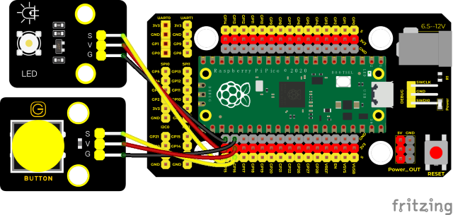
Run the test code
Double-click button control LED.py and click to run the test code.
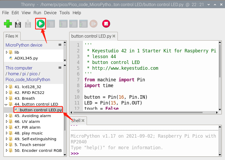
Test Code
'''
 * * Keyestudio 42 in 1 Starter Kit for Raspberry Pi Pico
 * lesson 44
 * button control LED
 * http://www.keyestudio.com
'''
from machine import Pin
import time

button = Pin(16, Pin.IN)
LED = Pin(15, Pin.OUT)
touch = False

def toggle_handle(pin):
    global touch
    touch = not touch

button.irq(trigger = Pin.IRQ_FALLING, handler = toggle_handle)

while True:
    LED.value(touch)
    time.sleep(0.01)
Code Explanation
1. button.irq(trigger = Pin.IRQ_FALLING, handler = toggle_handle): trigger mode is when high levels change into low levels, the trigger interrupts
2. toggle_handle: when entering the interrupt mode, the on and off of the LED can be controlled.
3. Set IO ports according to connection diagram and configure pins mode:
attachInterrupt(digitalPinToInterrupt(button), toggle_handle, FALLING)
The trigger mode is when a high level becomes a low level. When the trigger interrupts, the interrupt function will be activated.
toggle_handle: when entering the interrupt mode, the on and off of the LED can be controlled.
Test Result
Run the test code and press the button, LED will light up; if the button is pressed again, the LED will go out.
Upload the code wire up and power up with a USB cable. When the button is pressed, the LED will light up; when pressed again, the LED will go off.
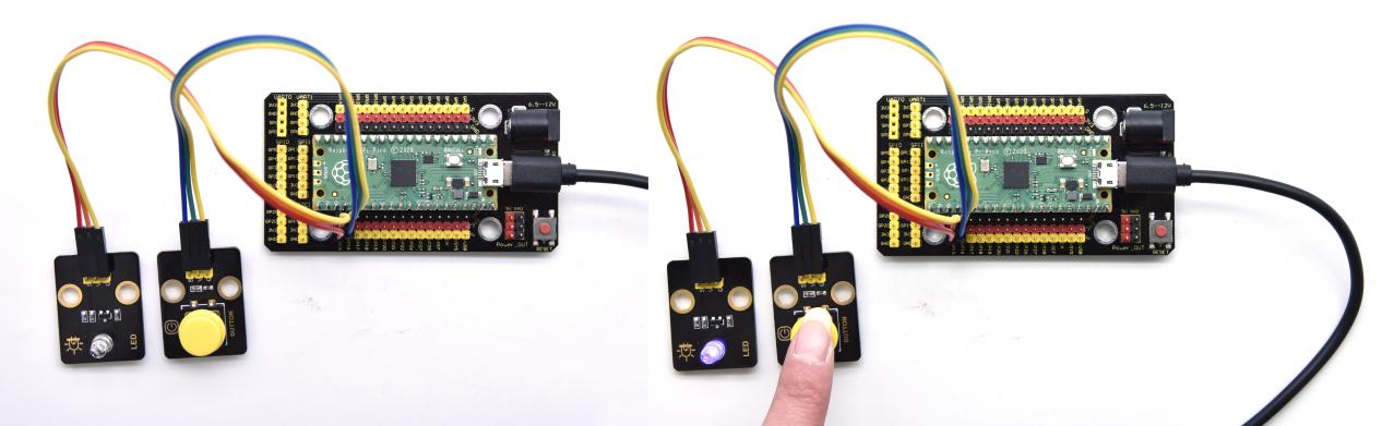
Project 45: Alarm Experiment

Overview
In the previous experiment, we control an output module though an input module. In this lesson, we will make an experiment that the active buzzer will emit sounds once an obstacle appears.
Components
|
|
|
|---|---|---|
Raspberry Pi Pico Board*1 |
Raspberry Pi Pico Expansion Board*1 |
Keyestudio Obstacle Avoidance Sensor*1 |
|
|
|
Micro USB Cable*1 |
3P Dupont Wire*2 |
Keyestudio Active Buzzer*1 |
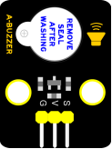
Connection Diagram
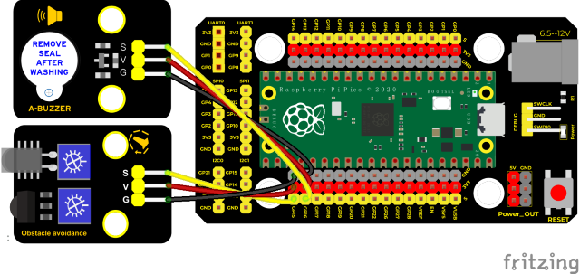
Run the test code
Click Avoiding alarm.py and double-click the code,and click to run the test code.
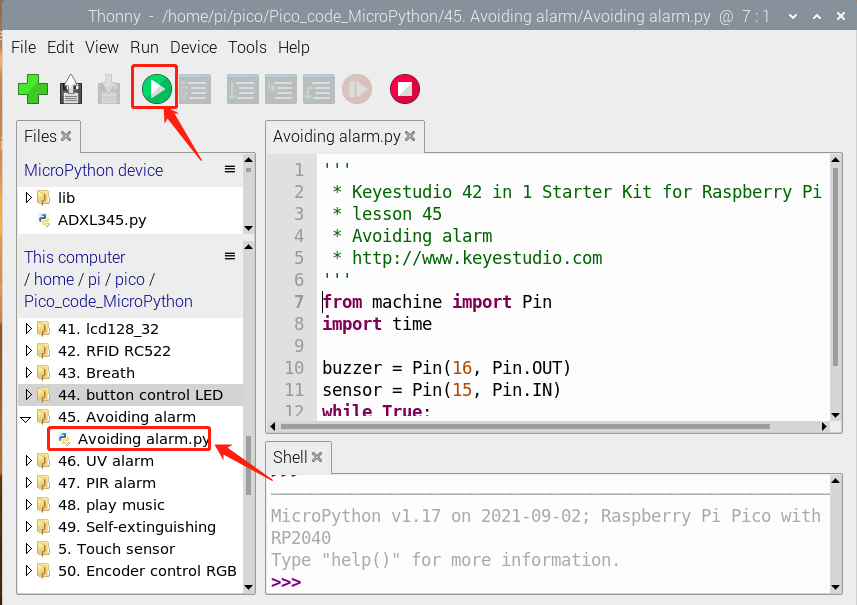
Test Code
'''
 * * Keyestudio 42 in 1 Starter Kit for Raspberry Pi Pico
 * lesson 45
 * Avoiding alarm
 * http://www.keyestudio.com
'''
from machine import Pin
import time

buzzer = Pin(16, Pin.OUT)
sensor = Pin(15, Pin.IN)
while True:
    buzzer.value(not(sensor.value()))
    time.sleep(0.01)
Code Explanation
1. When an obstacle is detected, sensor.value() will return a low level signal. So when an obstacle is detected, the GP16 connected to the buzzer pin will output a high level signal, the buzzer will emit sounds.
2. Set IO ports according to connection diagram then configure pins mode:
The value is 0 when pressing the button, So, we can determine the key value(0)through if (item == 0) and make the buzzer beep.
Test Result
Run the test code. The active buzzer will emit sound if detecting obstacles; otherwise, it won’t emit sound.
Upload the test code, if the obstacle is detected, the active buzzer will chime; if not, it won’t beep.
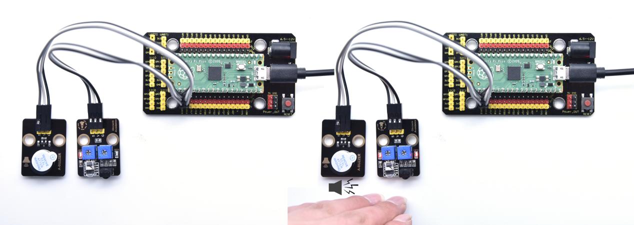
Project 46: Ultraviolet Alarm
Description
We can use a UV sensor to control the buzzer to achieve the effect of UV alarm.
Required Components
|
|
|
|---|---|---|
Raspberry Pi Pico Board*1 |
Raspberry Pi Pico Expansion Board*1 |
Keyestudio ultraviolet Sensor*1 |
|
|
|
3P Dupont Wire*2 |
Micro USB Cable*1 |
Keyestudio Active Buzzer*1 |
Connection Diagram
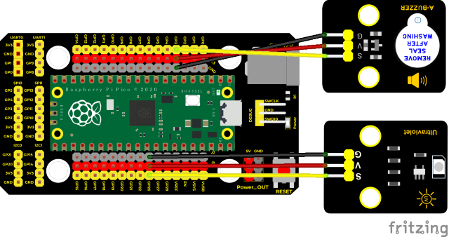
Run the test code
Find and double-click UV_alarm.py and click
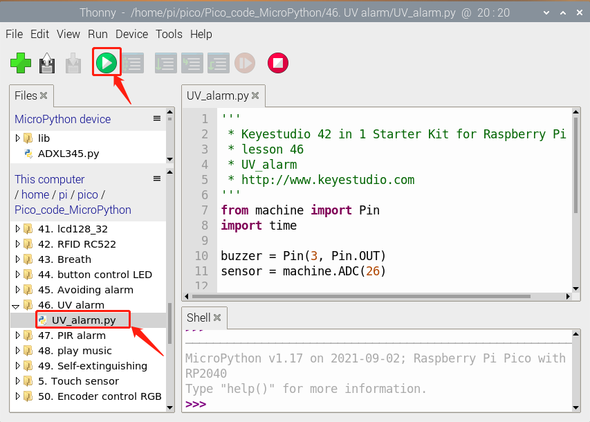
Test Code
'''
 * * Keyestudio 42 in 1 Starter Kit for Raspberry Pi Pico
 * lesson 46
 * UV_alarm
 * http://www.keyestudio.com
'''
from machine import Pin
import time

buzzer = Pin(3, Pin.OUT)
sensor = machine.ADC(26)

while True:
    analogVal = sensor.read_u16()
    print(analogVal)
    if analogVal > 1000:
        buzzer.value(1)
    else:
        buzzer.value(0)
    time.sleep(0.5)
Code Explanation
The code settings in the experiment are similar to the previous experiments. This time, the module we input is used as an analog sensor. By setting a threshold, the alarm exceeds the threshold.
Test Result
Wire up and run the test code. When detecting ultraviolet rays through he ultraviolet sensor and reaching the strength we set, the active buzzer will emit sound.
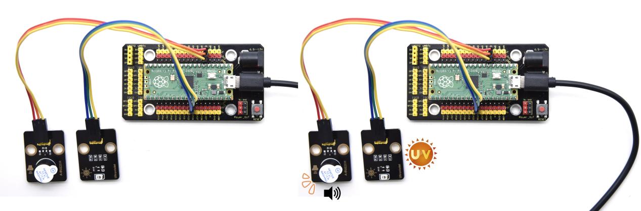
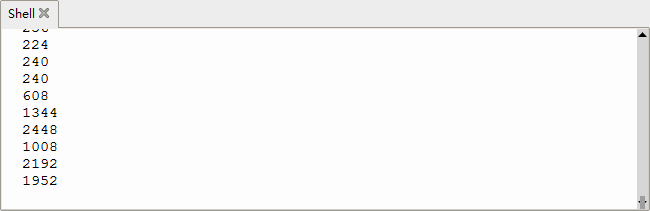
Project 47: Intrusion Detection
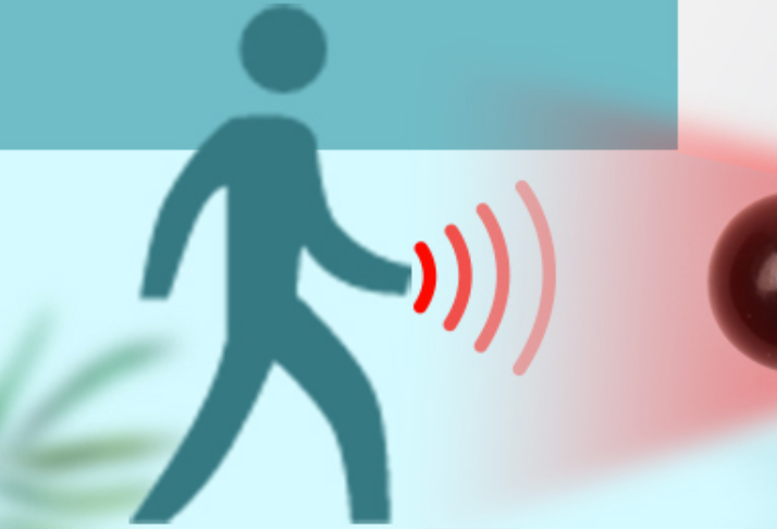
Description
In this experiment, we use a PIR motion sensor to control an active buzzer to emit sounds and the onboard LED to flash rapidly.
Required Components
|
|
|
|---|---|---|
Raspberry Pi Pico Board*1 |
Raspberry Pi Pico Expansion Board*1 |
Keyestudio DIY PIR Motion Sensor*1 |
|
|
|
3P Dupont Wire*2 |
Micro USB Cable*1 |
Keyestudio DIY Active Sensor*1 |
Connection Diagram
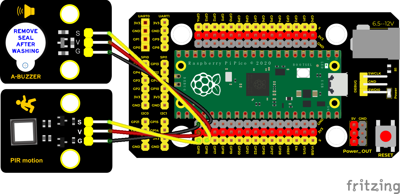
Run the test code
Find and double-click PIR alarm.py and click
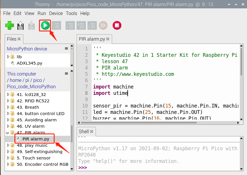
Test Code
'''
 * * Keyestudio 42 in 1 Starter Kit for Raspberry Pi Pico
 * lesson 47
 * PIR alarm
 * http://www.keyestudio.com
'''
import machine
import utime

sensor_pir = machine.Pin(15, machine.Pin.IN, machine.Pin.PULL_DOWN)
led = machine.Pin(25, machine.Pin.OUT)
buzzer = machine.Pin(16, machine.Pin.OUT)

def pir_handler(pin):
    utime.sleep_ms(100)
    if pin.value():
        print("Warning! Intrusion detected!")
        buzzer.value(1)
        for i in range(20):
            led.toggle()
            utime.sleep_ms(100)

sensor_pir.irq(trigger=machine.Pin.IRQ_RISING, handler=pir_handler)

while True:
    led.toggle()
    buzzer.value(0)
    utime.sleep(2)
Code Explanation
sensor_pir.irq(trigger=machine.Pin.IRQ_RISING, handler=pir_handler): low levels change into high levels. pir_handler is the interrupt function which can make the buzzer emit and LED flash
Test Result
After programming, the LED flashes slowly, the detector starts to work, and the interrupt trigger mode is IRQ_RISING. When there is an intrusion, the output level of the PIR changes from 0 to 1, the pir_handler() function will be called, the buzzer will emit sound, and the LED will flash quickly.
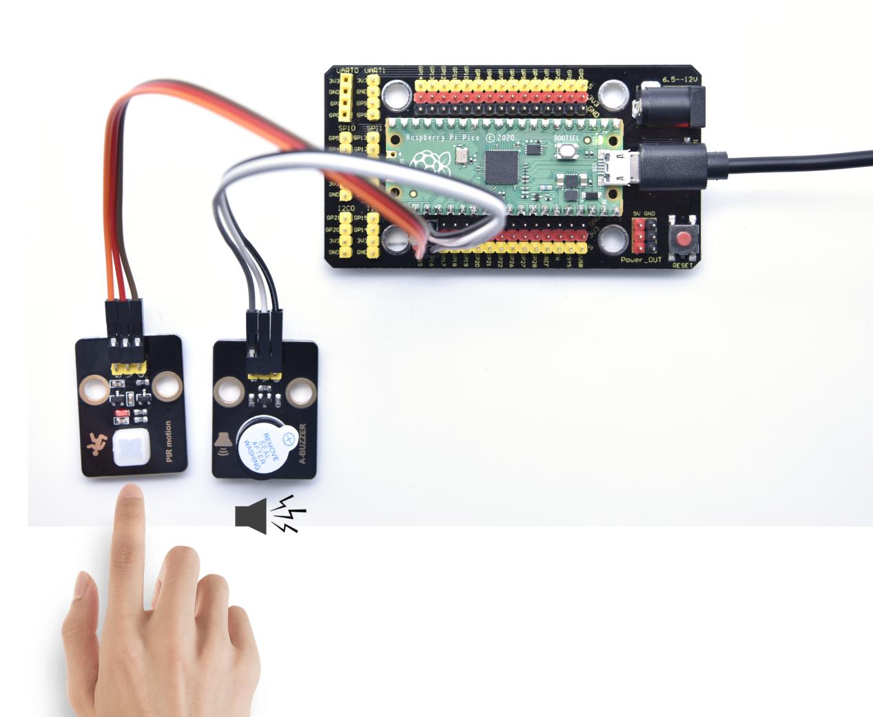
Project 48: Speaker Module

Introduction
We learned about controlling the speaker module to make sounds, play beats and adjust its volume. In fact, each song is a combination of specific beats and tones (frequencies). In this experiment, we use this speaker module to play a song.
The frequency of each tone is shown below.
Bass:
Key Note |
1~#~ |
2~#~ |
3~#~ |
4~#~ |
5~#~ |
6~#~ |
7~#~ |
|---|---|---|---|---|---|---|---|
A |
221 |
248 |
278 |
294 |
330 |
371 |
416 |
B |
248 |
278 |
294 |
330 |
371 |
416 |
467 |
C |
131 |
147 |
165 |
175 |
196 |
221 |
248 |
D |
147 |
165 |
175 |
196 |
221 |
248 |
278 |
E |
165 |
175 |
196 |
221 |
248 |
278 |
312 |
F |
175 |
196 |
221 |
234 |
262 |
294 |
330 |
G |
196 |
221 |
234 |
262 |
294 |
330 |
371 |
Midrange :
Key Note |
1 |
2 |
3 |
4 |
5 |
6 |
7 |
|---|---|---|---|---|---|---|---|
A |
441 |
495 |
556 |
589 |
661 |
724 |
833 |
B |
495 |
556 |
624 |
661 |
724 |
833 |
935 |
C |
262 |
294 |
330 |
350 |
393 |
441 |
495 |
D |
294 |
330 |
350 |
393 |
441 |
495 |
556 |
E |
330 |
350 |
393 |
441 |
495 |
556 |
624 |
F |
350 |
393 |
441 |
495 |
556 |
624 |
661 |
G |
393 |
441 |
495 |
556 |
624 |
661 |
724 |
Treble:
Key Note |
1^#^ |
2^#^ |
3^#^ |
4^#^ |
5^#^ |
6^#^ |
7^#^ |
|---|---|---|---|---|---|---|---|
A |
882 |
990 |
1112 |
1178 |
1322 |
1484 |
1665 |
B |
990 |
1112 |
1178 |
1322 |
1484 |
1665 |
1869 |
C |
525 |
589 |
661 |
700 |
786 |
882 |
990 |
D |
589 |
661 |
700 |
786 |
882 |
990 |
1112 |
E |
661 |
700 |
786 |
882 |
990 |
1112 |
1248 |
F |
700 |
786 |
882 |
935 |
1049 |
1178 |
1322 |
G |
786 |
882 |
990 |
1049 |
1178 |
1322 |
1484 |
Beats are the time delay for each note. The larger the number, the longer the delay time. A note without a line in the spectrum is a beat, with a delay of 1s. while a beat with an underline is 1/2 of a beat without a line, with a delay of 0.5s, and a beat with two underlines is 1/4 of a beat without a line, with a delay of 0.25s. The 1/8 of a beat is with a delay of 0.125s.
We will take Happy Birthday Song as an example.
Components
|
|
|
|---|---|---|
Raspberry Pi Pico Board*1 |
Raspberry Pi Pico Expansion Board*1 |
Keyestudio 8002b Audio Power Amplifier*1 |
|
|
|
3P Dupont Wire*1 |
Micro USB Cable*1 |
Connection Diagram
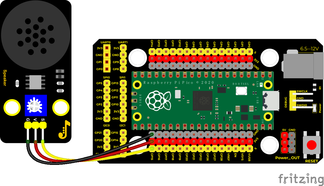
Run the test code
Find and double-click play music.py and click
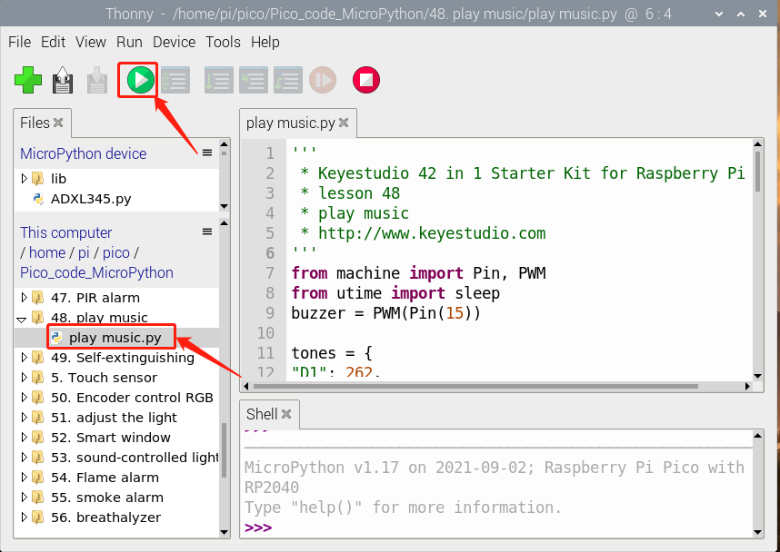
Test Code
'''
 * * Keyestudio 42 in 1 Starter Kit for Raspberry Pi Pico
 * lesson 48
 * play music
 * http://www.keyestudio.com
'''
from machine import Pin, PWM
from utime import sleep
buzzer = PWM(Pin(15))

tones = {
"D1": 262,
"D2": 293,
"D3": 329,
"D4": 349,
"D5": 392,
"D6": 440,
"D7": 494,
"M1": 523,
"M2": 586,
"M3": 658,
"M4": 697,
"M5": 783,
"M6": 879,
"M7": 987,
"H1": 1045,
"H2": 1171,
"H3": 1316,
"H4": 1393,
"H5": 1563,
"H6": 1755,
"H7": 1971
}

song = ["D5","D5","D6","D5","M1","D7",
        "D5","D5","D6","D5","M2","M1",
        "D5","D5","M5","M3","M1","D7","D6",
        "M4","M4","M3","M1","M2","M1"
]

durt = [0.25, 0.25, 0.5, 0.5, 0.5, 1,
       0.25, 0.25, 0.5, 0.5, 0.5, 1,
       0.25, 0.25, 0.5, 0.5, 0.5, 0.5, 0.5,
       0.25, 0.25, 0.5, 0.5, 0.5, 1
]

def playtone(frequency):
    buzzer.duty_u16(1000)
    buzzer.freq(frequency)

def bequiet():
    buzzer.duty_u16(0)

def playsong(mysong):
    for i in range(len(mysong)):
        playtone(tones[mysong[i]])
        sleep(durt[i])
    bequiet()
playsong(song)
Code Explanation
We list frequencies of all D keys. Then list the frequencies and beats according to the musical notation. The beat we use is 500ms and can be adjusted. The corresponding beat are looped to become a song.
Test Result
Connect the components according to the connection diagram and run the test code, the audio power amplifier module will play a birthday song.
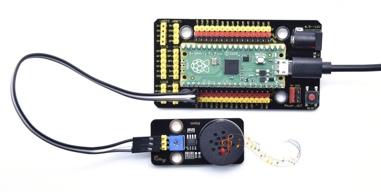
Project 49: Extinguishing Robot

Description
Today we will use Arduino simulation to build an extinguishing robot that will automatically sense the fire and start the fan.
In this project we will learn how to build a very simple robot using pico, (detecting flames with a flame sensor, blowing out candles with a fan) can teach us basic concepts about robotics. Once you understand the basics below, you can build more complex robots.
Components Required
|
|
|
|---|---|---|
Raspberry Pi Pico Board*1 |
Raspberry Pi Pico Expansion Board*1 |
130 Motor*1 |
|
|
|
4P Dupont Wire*2 |
Micro USB Cable*1 |
Flame Sensor*1 |
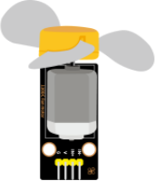
Connection Diagram
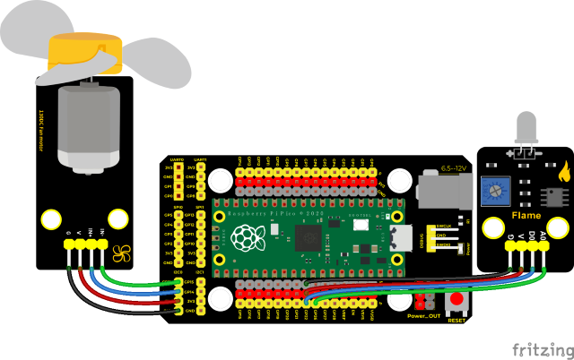
Run the test code
Double-click Self-extinguishing.py,and clickto run the test code.
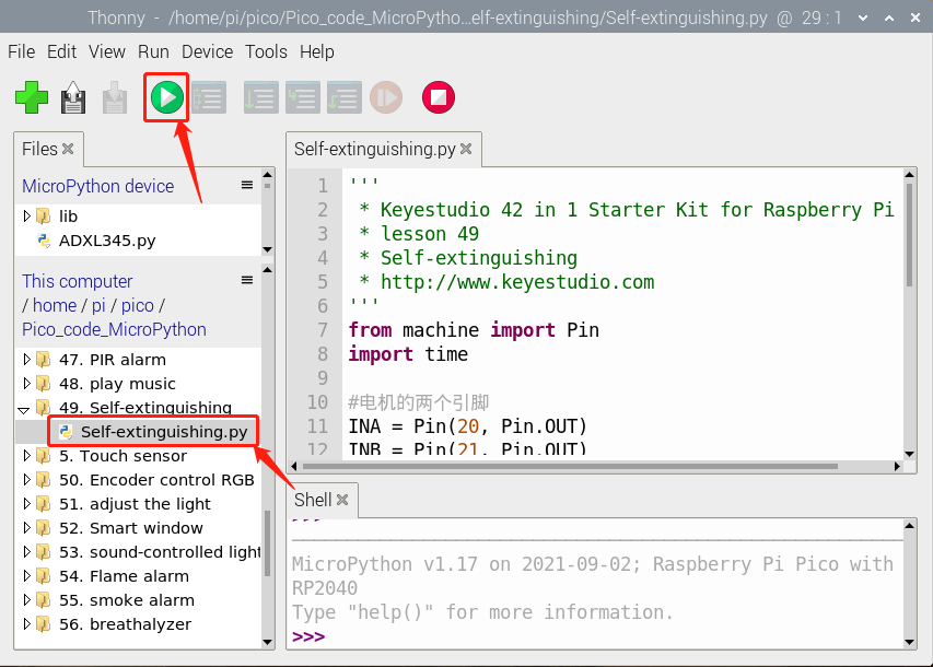
Test Code
'''
 * Keyestudio 42 in 1 Starter Kit for Raspberry Pi Pico
 * lesson 49
 * Self-extinguishing
 * http://www.keyestudio.com
'''
from machine import Pin
import time

#two pins of motors
INA = Pin(20, Pin.OUT)
INB = Pin(21, Pin.OUT)

flame_A = machine.ADC(26)

while True:
    value = flame_A.read_u16()
    print(value)
    if value < 30000:
        #start
        INA.value(0)
        INB.value(1)
    else:
        #stop
        INA.value(0)
        INB.value(0)
    time.sleep(0.1)
Code Explanation
In the code, we set the threshold value to 30000. When the analog value detected by the flame sensor is lower than the threshold value, the fan will be automatically turned on; otherwise, it will be turned off. For the driving method of the fan, please refer to the 130 Motor.
Test Result
Wire up and upload the test code,the shell shows the flame value. When this value is less than 30000, the fan will works to blow out the fire. Basically, the flame value can be set by yourself.
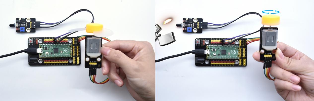
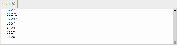
Project 50: Rotary Encoder
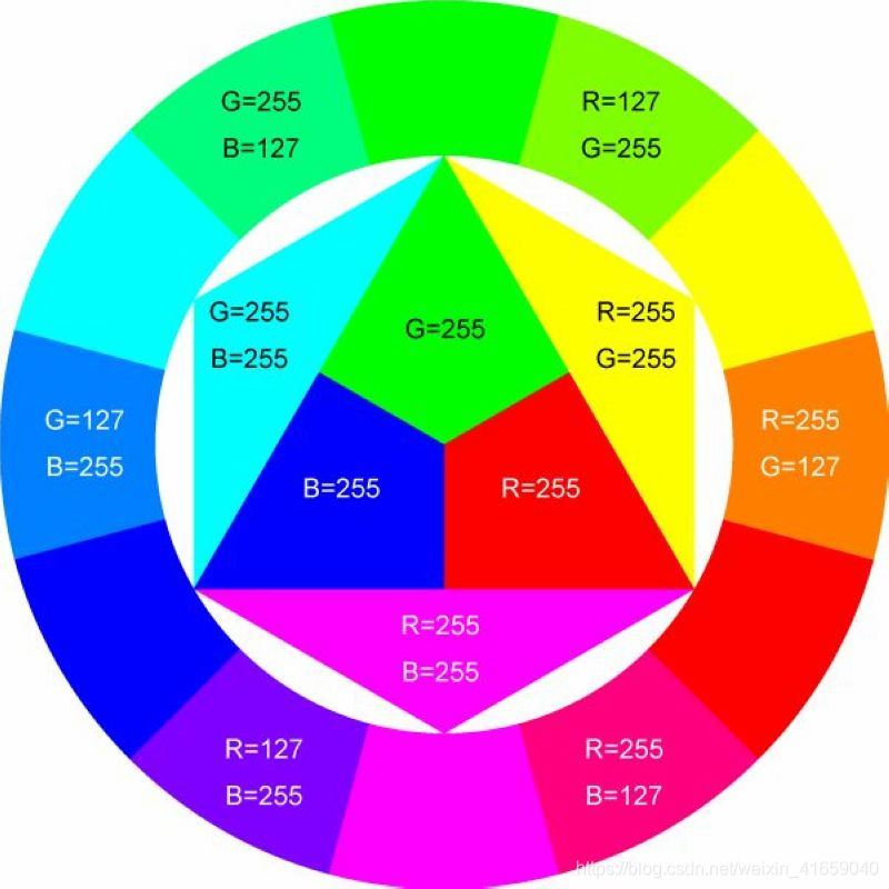
Introduction
In this lesson, we will control the LED on the RGB module to show different colors through a rotary encoder.
When designing the code, we need to divide the obtained values by 3 to get the remainders. The remainder is 0 and the LED will become red. The remainder is 1, the LED will become green. The remainder is 2, the LED will turn blue.
Components
|
|
|
|
|---|---|---|---|
Raspberry Pi Pico Board*1 |
Raspberry Pi Pico Expansion Board*1 |
Keyestudio Common Cathode RGB Module*1 |
Keyestudio Rotary Encoder Module*1 |
|
|
|
|
5P Dupont Wire*1 |
4P Dupont Wire*1 |
Micro USB Cable*1 |
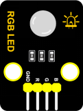
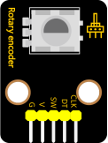
Connection Diagram
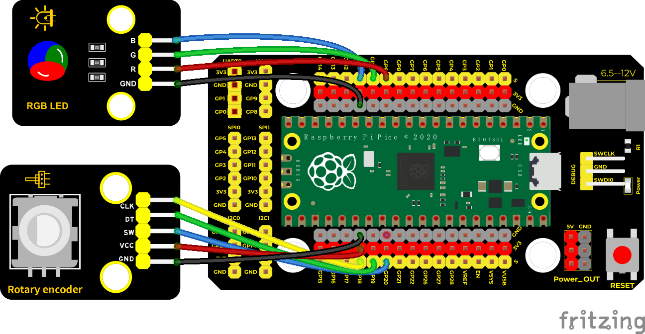
Run the test code
Double-click Encoder control RGB.py,and clickto run the test code.
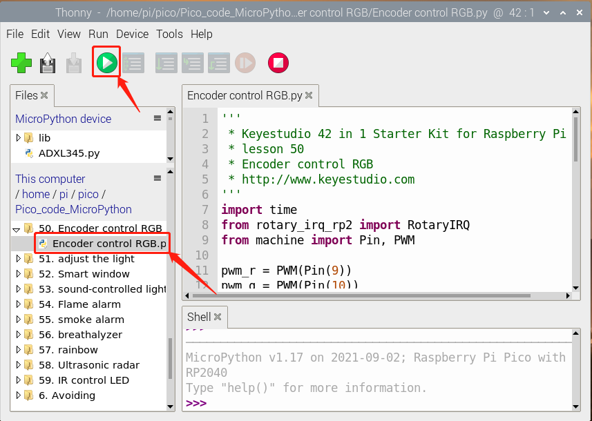
Test Code
'''
 * * Keyestudio 42 in 1 Starter Kit for Raspberry Pi Pico
 * lesson 50
 * Encoder control RGB
 * http://www.keyestudio.com
'''
import time
from rotary_irq_rp2 import RotaryIRQ
from machine import Pin, PWM

pwm_r = PWM(Pin(9))
pwm_g = PWM(Pin(10))
pwm_b = PWM(Pin(11))

pwm_r.freq(1000)
pwm_g.freq(1000)
pwm_b.freq(1000)

def light(red, green, blue):
    pwm_r.duty_u16(red)
    pwm_g.duty_u16(green)
    pwm_b.duty_u16(blue)

SW=Pin(20,Pin.IN,Pin.PULL_UP)
r = RotaryIRQ(pin_num_clk=18,
              pin_num_dt=19,
              min_val=0,
              reverse=False,
              range_mode=RotaryIRQ.RANGE_UNBOUNDED)

while True:
    val = r.value()
    print(val%3)
    if val%3 == 0:
        light(65535, 0, 0)
    elif val%3 == 1:
        light(0, 65535, 0)
    elif val%3 == 2:
        light(0, 0, 65535)
    time.sleep(0.1)
Code Explanation
In the experiment, we set the val to the remainder of Encoder_Count divided by 3. Encoder_Count is the value of the encoder. Then we can set pin 9(red), 10(green) and 11(blue) according to remainders.
Colors of LED can be controlled by remainders.
Test Result
Wire up, run the code and open the serial monitor. Rotate the knob of the rotary encoder to display the reminders, which can control colors of LED.
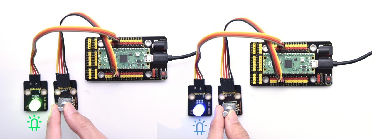
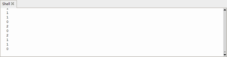
Project 51: Rotary Potentiometer

Introduction
In the previous courses, we did experiments of breathing light and controlling LED with button. In this course, we do these two experiments by controlling the brightness of LED through an adjustable potentiometer. The brightness of LED is controlled by PWM values, and the range of analog values is the same as the PWM’s, from 0 to 65535.
After the code is set successfully, we can control the brightness of the LED on the module by rotating the potentiometer.
Required Components
|
|
|
|---|---|---|
Raspberry Pi Pico Board*1 |
Raspberry Pi Pico Expansion Board*1 |
Keyestudio Purple LED*1 |
|
|
|
3P Dupont Wire*2 |
Micro USB Cable*1 |
Keyestudio Rotary Potentiometer*1 |
Connection Diagram
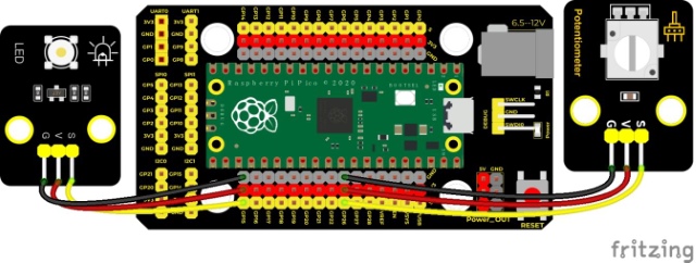
Run the test code
Double-click adjust the light.py,and clickto run the test code.
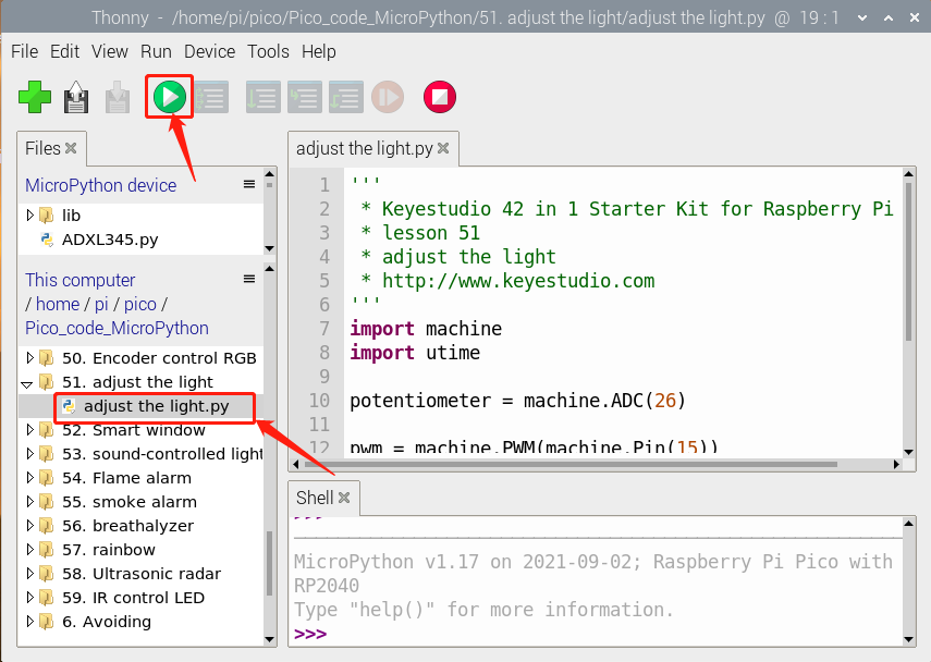
Test Code
'''
 * * Keyestudio 42 in 1 Starter Kit for Raspberry Pi Pico
 * lesson 51
 * adjust the light
 * http://www.keyestudio.com
'''
import machine
import utime

potentiometer = machine.ADC(26)

pwm = machine.PWM(machine.Pin(15))
pwm.freq(1000)

while True:
    pot_value = potentiometer.read_u16()
    pwm.duty_u16(pot_value)
    utime.sleep(0.1)
Code Explanation
It is easy to control the brightness of the LED light by a potentiometer. Here we can find that MicroPython unifies the value range of the ADC between 0 and 65535, and assigns values directly, which is simple and convenient.
Test Result
Run the test code and turn the potentiometer on the module to adjust the brightness of the LED on the LED module.
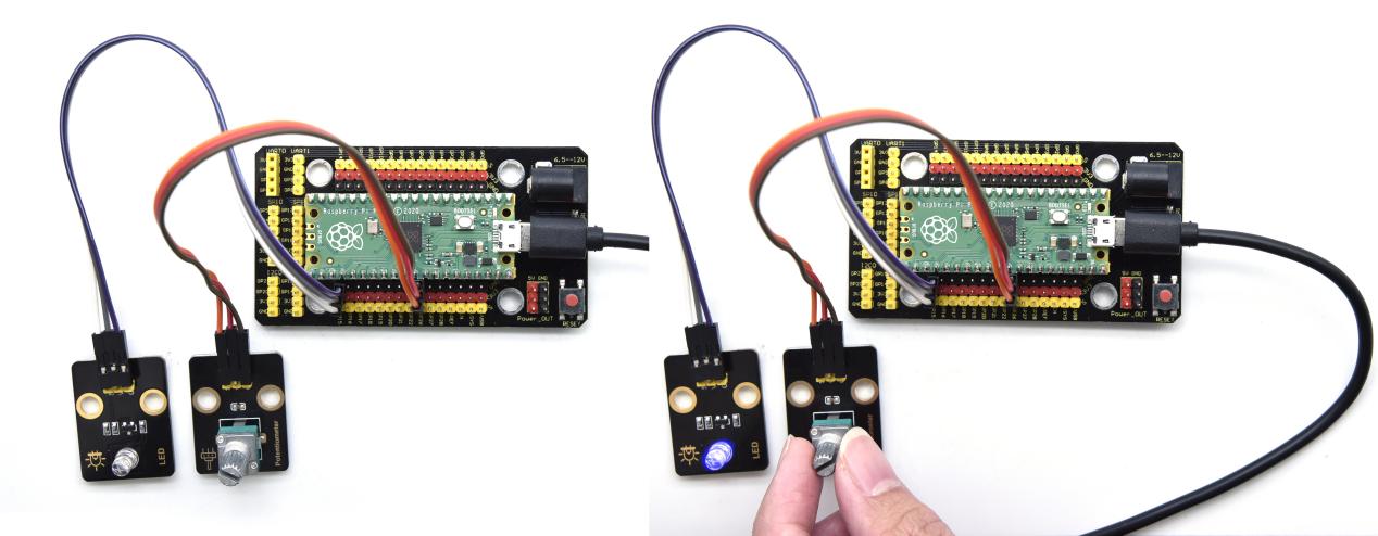
Project 52: Smart Windows

Description
In life, we can see all kinds of smart products, such as smart home. Smart homes include smart curtains, smart windows, smart TVs, smart lights, and more. In this experiment, we use a steam sensor to detect rainwater, and then achieve the effect of closing and opening the window by a servo.
Required Components
|
|
|
|---|---|---|
Raspberry Pi Pico Board*1 |
Raspberry Pi Pico Expansion Board*1 |
Keyestudio Steam Sensor*1 |
|
|
|
3P Dupont Wire*1 |
Micro USB Cable*1 |
Servo*1 |
Connection Diagram
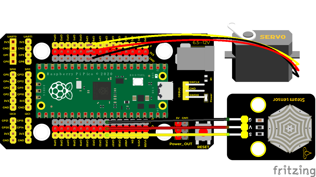
Run the test code
Find and double-click button control LED.py and click
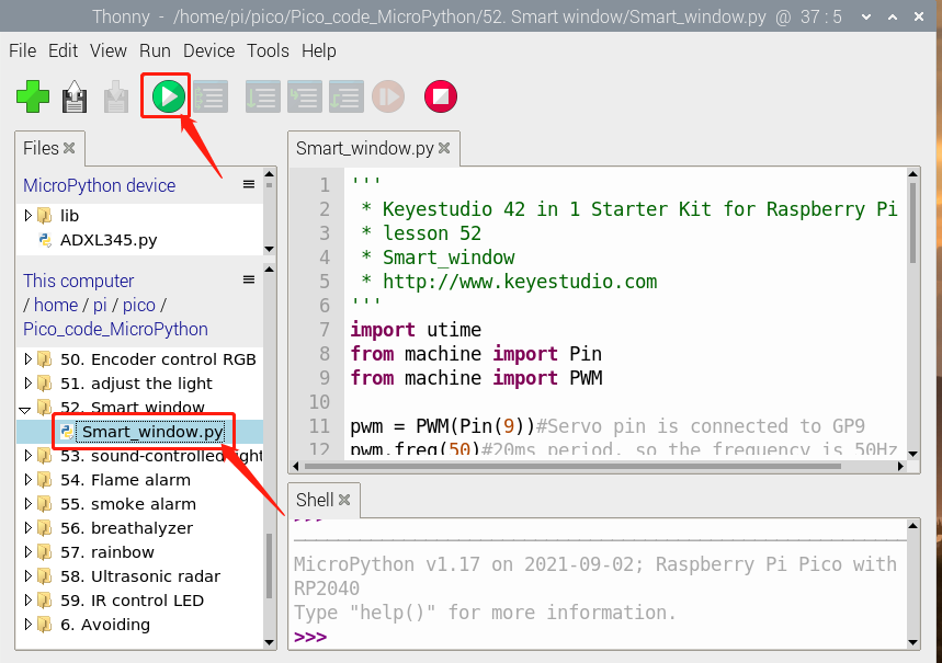
Test Code
'''
 * * Keyestudio 42 in 1 Starter Kit for Raspberry Pi Pico
 * lesson 52
 * Smart_window
 * http://www.keyestudio.com
'''
import utime
from machine import Pin
from machine import PWM

pwm = PWM(Pin(9))#the pin of the servo is connected to GP9
pwm.freq(50)#20ms,frequency is 50Hz
sensor = machine.ADC(26)#ADC0
'''
The duty cycle corresponding to the angle
0°----2.5%----1638
45°----5%----3276
90°----7.5%----4915
135°----10%----6553
180°----12.5%----8192
Take consideration into errors,set duty cycle in the range of 1000~9000,then rotate 0~180°
'''
angle_0 = 1638
angle_90 = 4915
angle_180 = 8192

while True:
    value = sensor.read_u16()
    print(value)
    if value > 2000:
        pwm.duty_u16(angle_0)
        utime.sleep(0.5)
    else:
        pwm.duty_u16(angle_180)
        utime.sleep(0.5)
Code Explanation
We can control a servo to rotate by a threshold
Test Result
Wire up and run the test code. When the sensor detects a certain amount of water, the servo rotates to achieve the effect of closing or opening windows.
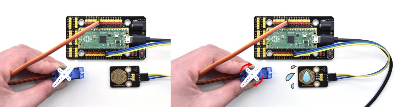
Project 53: Sound Activated Light

Introduction
In this lesson, we will make a smart sound activated light using a sound sensor and an LED module. When we make a sound, the light will automatically turn on; when there is no sound, the lights will automatically turn off.
How it works? Because the sound-controlled light is equipped with a sound sensor, and this sensor converts the intensity of external sound into a corresponding value. Then set a threshold, when the threshold is exceeded, the light will turn on, and when it is not exceeded, the light will go out.
Components
|
|
|
|---|---|---|
Raspberry Pi Pico Board*1 |
Raspberry Pi Pico Shield*1 |
Keyestudio Sound Sensor*1 |
|
|
|
3P Dupont Wire*2 |
Micro USB Cable*1 |
Keyestudio White LED Module*1 |
Connection Diagram
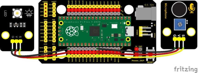
Run the Test Code
Double-click sound-controlled lights.py and click to run the test code.
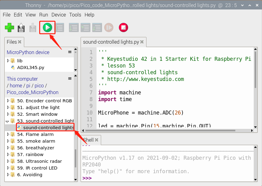
Test Code
'''
 * * Keyestudio 42 in 1 Starter Kit for Raspberry Pi Pico
 * lesson 53
 * sound-controlled lights
 * http://www.keyestudio.com
'''
import machine
import time

MicroPhone = machine.ADC(26)

led = machine.Pin(15,machine.Pin.OUT)

while True:
    value = MicroPhone.read_u16()
    print(value)
    if value > 5000:
        led.value(1)
        time.sleep(3)
    else:
        led.value(0)
    time.sleep(0.1)
Code Explanation
We set the analog threshold value to 5000. If more than 5000, LED will be on 3s; on the contrary, it will be off.
Test Result
Run the test code, the shell monitor displays the corresponding volume value. When the analog value of sound is greater than 5000, the LED on the LED module will light up, otherwise it will go off.
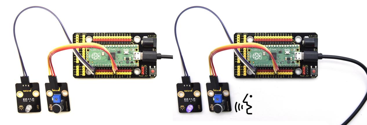
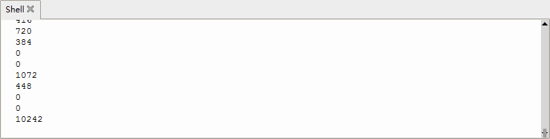
Project 54: Fire Alarm

Description
In this experiment, we will make a fire alarm system. Just use a flame sensor to control an active buzzer to emit sounds.
Required Components
|
|
|
|
|---|---|---|---|
Raspberry Pi Pico Board*1 |
Raspberry Pi Pico Expansion Board*1 |
Keyestudio DIY Active Buzzer*1 |
keyestudio DIY Flame Sensor*1 |
|
|
|
|
Micro USB Cable*1 |
3P Dupont Wire*1 |
4P Dupont Wire*1 |
Connection Diagram
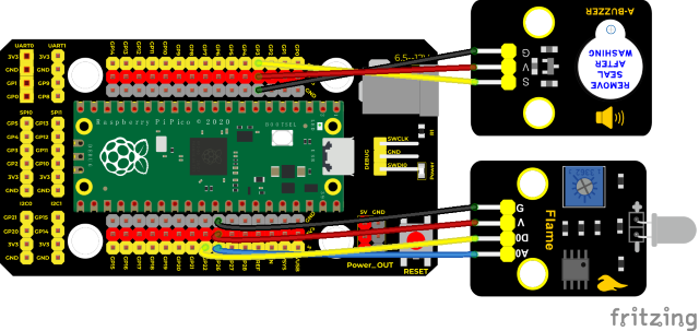
Run the test code
Find and double-click Flame_alarm.py and click
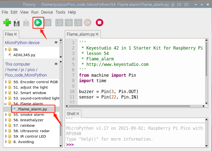
Test Code
'''
 * * Keyestudio 42 in 1 Starter Kit for Raspberry Pi Pico
 * lesson 54
 * Flame_alarm
 * http://www.keyestudio.com
'''
from machine import Pin
import time

buzzer = Pin(3, Pin.OUT)
sensor = Pin(22, Pin.IN)

while True:
    analogVal = sensor.value()
    print(analogVal)
    if analogVal == 0:
        buzzer.value(1)
    else:
        buzzer.value(0)
    time.sleep(0.5)
Code Explanation
This flame sensor uses an analog pin and a digital pin. When a flame is detected, the digital pin outputs a low level. In this experiment we will use the digital port.
Test Result
Wire up, run the test code and power on. The sensor detects the flame, and the external active buzzer will emit sounds, otherwise the active buzzer will not emit sounds.
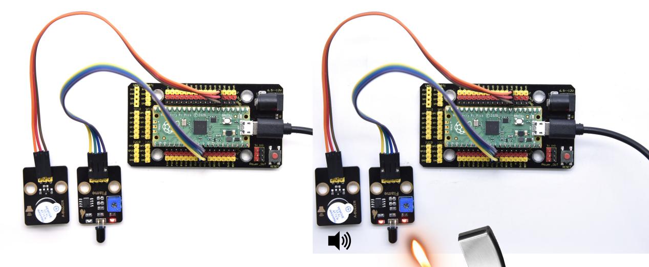
Project 55: Smoke Alarm

Description
In this experiment, we will make a smoke alarm by a TM16504-Digit segment module, a gas sensor and an active buzzer.
Required Components
|
|
|
|
|---|---|---|---|
Raspberry Pi Pico Board*1 |
Raspberry Pi Pico Expansion Board*1 |
Keyestudio Active Buzzer*1 |
Keyestudio TM16504-Digit Segment Module*1 |
|
|
|
|
keyestudio Analog Gas Senso*1 |
3P Dupont Wire*1 |
4P Dupont Wire*2 |
Micro USB Cable*1 |
Connection Diagram
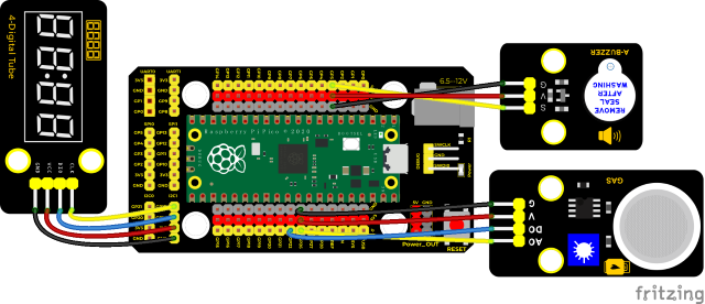
Run the test code
Find and double-click smoke_alarm.py and click.
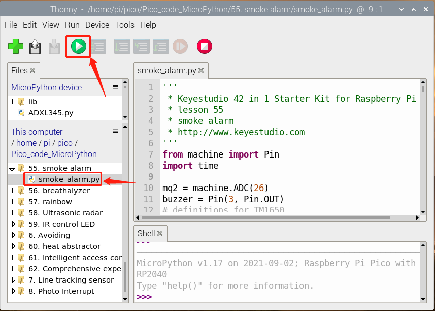
Test Code
'''
 * * Keyestudio 42 in 1 Starter Kit for Raspberry Pi Pico
 * lesson 55
 * smoke_alarm
 * http://www.keyestudio.com
'''
from machine import Pin
import time

mq2 = machine.ADC(26)
buzzer = Pin(3, Pin.OUT)
# definitions for TM1650
ADDR_DIS = 0x48  #mode command
ADDR_KEY = 0x49  #read key value command

# definitions for brightness
BRIGHT_DARKEST = 0
BRIGHT_TYPICAL = 2
BRIGHTEST      = 7

on  = 1
off = 0

# number:0~9
NUM = [0x3f,0x06,0x5b,0x4f,0x66,0x6d,0x7d,0x07,0x7f,0x6f]
# DIG = [0x68,0x6a,0x6c,0x6e]
DIG = [0x6e,0x6c,0x6a,0x68]
DOT = [0,0,0,0]

clkPin = 15
dioPin = 14
clk = machine.Pin(clkPin, machine.Pin.OUT)
dio = machine.Pin(dioPin, machine.Pin.OUT)

DisplayCommand = 0

def writeByte(wr_data):
    global clk,dio
    for i in range(8):
        if(wr_data & 0x80 == 0x80):
            dio.value(1)
        else:
            dio.value(0)
        clk.value(0)
        time.sleep(0.0001)
        clk.value(1)
        time.sleep(0.0001)
        clk.value(0)
        wr_data <<= 1
    return

def start():
    global clk,dio
    dio.value(1)
    clk.value(1)
    time.sleep(0.0001)
    dio.value(0)
    return

def ack():
    global clk,dio
    dy = 0
    clk.value(0)
    time.sleep(0.0001)
    dio = Pin(dioPin, machine.Pin.IN)
    while(dio.value() == 1):
        time.sleep(0.0001)
        dy += 1
        if(dy>5000):
            break
    clk.value(1)
    time.sleep(0.0001)
    clk.value(0)
    dio = Pin(dioPin, machine.Pin.OUT)
    return

def stop():
    global clk,dio
    dio.value(0)
    clk.value(1)
    time.sleep(0.0001)
    dio.value(1)
    return

def displayBit(bit, num):
    global ADDR_DIS
    if(num > 9 and bit > 4):
        return
    start()
    writeByte(ADDR_DIS)
    ack()
    writeByte(DisplayCommand)
    ack()
    stop()
    start()
    writeByte(DIG[bit-1])
    ack()
    if(DOT[bit-1] == 1):
        writeByte(NUM[num] | 0x80)
    else:
        writeByte(NUM[num])
    ack()
    stop()
    return

def clearBit(bit):
    if(bit > 4):
        return
    start()
    writeByte(ADDR_DIS)
    ack()
    writeByte(DisplayCommand)
    ack()
    stop()
    start()
    writeByte(DIG[bit-1])
    ack()
    writeByte(0x00)
    ack()
    stop()
    return


def setBrightness(b = BRIGHT_TYPICAL):
    global DisplayCommand,brightness
    DisplayCommand = (DisplayCommand & 0x0f)+(b<<4)
    return

def setMode(segment = 0):
    global DisplayCommand
    DisplayCommand = (DisplayCommand & 0xf7)+(segment<<3)
    return

def displayOnOFF(OnOff = 1):
    global DisplayCommand
    DisplayCommand = (DisplayCommand & 0xfe)+OnOff
    return

def displayDot(bit, OnOff):
    if(bit > 4):
        return
    if(OnOff == 1):
        DOT[bit-1] = 1;
    else:
        DOT[bit-1] = 0;
    return

def InitDigitalTube():
    setBrightness(2)
    setMode(0)
    displayOnOFF(1)
    for _ in range(4):
        clearBit(_)
    return

def ShowNum(num): #0~9999
    displayBit(1,num%10)
    if(num < 10):
        clearBit(2)
        clearBit(3)
        clearBit(4)
    if(num > 9 and num < 100):
        displayBit(2,num//10%10)
        clearBit(3)
        clearBit(4)
    if(num > 99 and num < 1000):
        displayBit(2,num//10%10)
        displayBit(3,num//100%10)
        clearBit(4)
    if(num > 999 and num < 10000):
        displayBit(2,num//10%10)
        displayBit(3,num//100%10)
        displayBit(4,num//1000)

InitDigitalTube()

while True:
    value = mq2.read_u16()//16
    print(value)
    ShowNum(value)
    if value > 1000:
        buzzer.value(1)
    else:
        buzzer.value(0)
    time.sleep(0.1)
Code Explanation
Define an integer variable val to store the analog value of the smoke sensor, and then we display the analog value in the four-digit digital tube, and then set a threshold, and when the threshold is reached, the buzzer will sound.
Test Result
Run the test code, wire up and power on. When the concentration of combustible gas exceeds the standard, the active buzzer module will give an alarm, and the four-digit digital tube will display the concentration value.
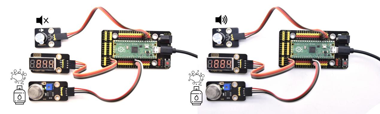
Project 56: Alcohol Sensor

Description
In the last experiment, we made a smoke alarm. In this experiment, we combine the active buzzer, the MQ-3 alcohol sensor, and a four-digit digital tube to test the alcohol concentration through the alcohol sensor. Then, the concentration to control the active buzzer alarm and the four-digit digital tube to display the concentration. So as to achieve the simulation effect of alcohol detector.
Components Required
|
|
|
|
|---|---|---|---|
Raspberry Pi Pico Board*1 |
Raspberry Pi Pico Expansion Board*1 |
Active Buzzer |
Keyestudio TM1650 4-Digit Module*1 |
|
|
|
|
keyestudio Alcohol Sensor*1 |
3P Dupont Wire*1 |
4P Dupont Wire*2 |
Micro USB Cable*1 |
Connection Diagram
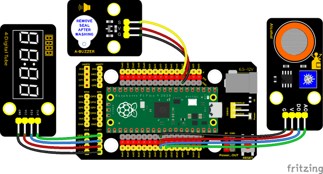
Run the test code
Find the breathalyzer.py and double-click the code and click 。
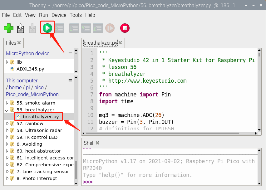
Code Explanation
Define an integer variable val to store the analog value of the alcohol sensor, then we display the analog value in the four-digit display module and set a threshold.
Test Result
Wire up according to the wiring diagram and run the test code. When different alcohol concentrations are detected, the active buzzer module will alarm, and the four-digit digital display will show the concentration value.
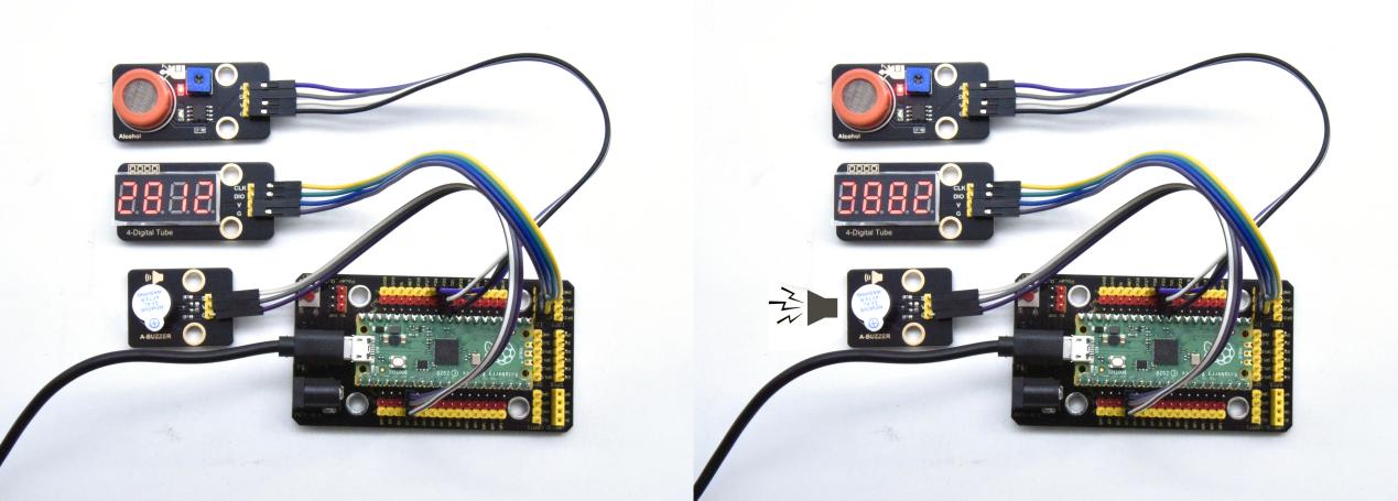
Test Code
'''
 * Keyestudio 42 in 1 Starter Kit for Raspberry Pi Pico
 * lesson 56
 * breathalyzer
 * http://www.keyestudio.com
'''
from machine import Pin
import time

mq3 = machine.ADC(26)
buzzer = Pin(3, Pin.OUT)
# definitions for TM1650
ADDR_DIS = 0x48  #mode command
ADDR_KEY = 0x49  #read key value command

# definitions for brightness
BRIGHT_DARKEST = 0
BRIGHT_TYPICAL = 2
BRIGHTEST      = 7

on  = 1
off = 0

# number:0~9
NUM = [0x3f,0x06,0x5b,0x4f,0x66,0x6d,0x7d,0x07,0x7f,0x6f]
# DIG = [0x68,0x6a,0x6c,0x6e]
DIG = [0x6e,0x6c,0x6a,0x68]
DOT = [0,0,0,0]

clkPin = 15
dioPin = 14
clk = machine.Pin(clkPin, machine.Pin.OUT)
dio = machine.Pin(dioPin, machine.Pin.OUT)

DisplayCommand = 0

def writeByte(wr_data):
    global clk,dio
    for i in range(8):
        if(wr_data & 0x80 == 0x80):
            dio.value(1)
        else:
            dio.value(0)
        clk.value(0)
        time.sleep(0.0001)
        clk.value(1)
        time.sleep(0.0001)
        clk.value(0)
        wr_data <<= 1
    return

def start():
    global clk,dio
    dio.value(1)
    clk.value(1)
    time.sleep(0.0001)
    dio.value(0)
    return

def ack():
    global clk,dio
    dy = 0
    clk.value(0)
    time.sleep(0.0001)
    dio = Pin(dioPin, machine.Pin.IN)
    while(dio.value() == 1):
        time.sleep(0.0001)
        dy += 1
        if(dy>5000):
            break
    clk.value(1)
    time.sleep(0.0001)
    clk.value(0)
    dio = Pin(dioPin, machine.Pin.OUT)
    return

def stop():
    global clk,dio
    dio.value(0)
    clk.value(1)
    time.sleep(0.0001)
    dio.value(1)
    return

def displayBit(bit, num):
    global ADDR_DIS
    if(num > 9 and bit > 4):
        return
    start()
    writeByte(ADDR_DIS)
    ack()
    writeByte(DisplayCommand)
    ack()
    stop()
    start()
    writeByte(DIG[bit-1])
    ack()
    if(DOT[bit-1] == 1):
        writeByte(NUM[num] | 0x80)
    else:
        writeByte(NUM[num])
    ack()
    stop()
    return

def clearBit(bit):
    if(bit > 4):
        return
    start()
    writeByte(ADDR_DIS)
    ack()
    writeByte(DisplayCommand)
    ack()
    stop()
    start()
    writeByte(DIG[bit-1])
    ack()
    writeByte(0x00)
    ack()
    stop()
    return


def setBrightness(b = BRIGHT_TYPICAL):
    global DisplayCommand,brightness
    DisplayCommand = (DisplayCommand & 0x0f)+(b<<4)
    return

def setMode(segment = 0):
    global DisplayCommand
    DisplayCommand = (DisplayCommand & 0xf7)+(segment<<3)
    return

def displayOnOFF(OnOff = 1):
    global DisplayCommand
    DisplayCommand = (DisplayCommand & 0xfe)+OnOff
    return

def displayDot(bit, OnOff):
    if(bit > 4):
        return
    if(OnOff == 1):
        DOT[bit-1] = 1;
    else:
        DOT[bit-1] = 0;
    return

def InitDigitalTube():
    setBrightness(2)
    setMode(0)
    displayOnOFF(1)
    for _ in range(4):
        clearBit(_)
    return

def ShowNum(num): #0~9999
    displayBit(1,num%10)
    if(num < 10):
        clearBit(2)
        clearBit(3)
        clearBit(4)
    if(num > 9 and num < 100):
        displayBit(2,num//10%10)
        clearBit(3)
        clearBit(4)
    if(num > 99 and num < 1000):
        displayBit(2,num//10%10)
        displayBit(3,num//100%10)
        clearBit(4)
    if(num > 999 and num < 10000):
        displayBit(2,num//10%10)
        displayBit(3,num//100%10)
        displayBit(4,num//1000)

InitDigitalTube()

while True:
    value = mq3.read_u16()//16
    print(value)
    ShowNum(value)
    if value > 3000:
        buzzer.value(1)
    else:
        buzzer.value(0)
    time.sleep(0.1)
Project 57: 6812 Colorful LED

Description
We learned how to use the 6812 RGB module, we knew that this module can light up each LED through a pin. In this experiment, we will control the RGB module to display different colors.
(Note: do not look directly at the LEDs for a long time to avoid damage to our eyes.)
Required Components
|
|
|
|---|---|---|
Raspberry Pi Pico Board*1 |
Raspberry Pi Pico Shield*1 |
Keyestudio 6812 RGB Module*1 |
|
|
|
3P Dupont Wire*1 |
Micro USB Cable*1 |
Connection Diagram
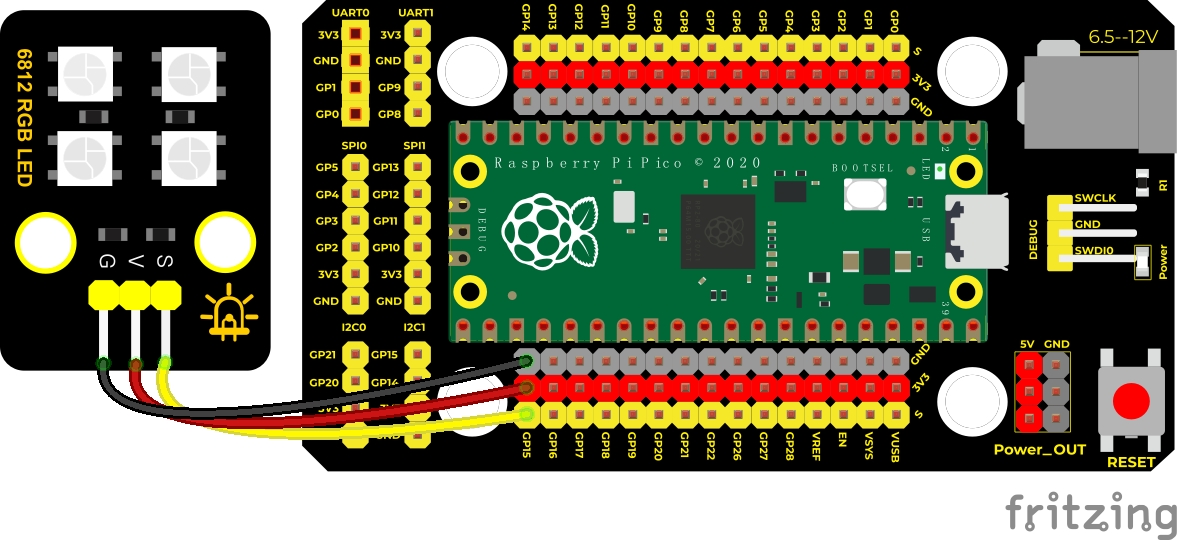
Run the test code
Double-click 6812.py and click to run the test code.
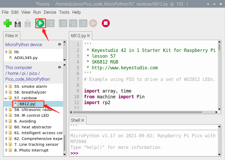
Test Code
'''
 * * Keyestudio 42 in 1 Starter Kit for Raspberry Pi Pico
 * lesson 57
 * SK6812 RGB
 * http://www.keyestudio.com
'''
# Example using PIO to drive a set of WS2812 LEDs.

import array, time
from machine import Pin
import rp2

# Configure the number of WS2812 LEDs.
NUM_LEDS = 4
PIN_NUM = 15
brightness = 0.2

@rp2.asm_pio(sideset_init=rp2.PIO.OUT_LOW, out_shiftdir=rp2.PIO.SHIFT_LEFT, autopull=True, pull_thresh=24)
def ws2812():
    T1 = 2
    T2 = 5
    T3 = 3
    wrap_target()
    label("bitloop")
    out(x, 1)               .side(0)    [T3 - 1]
    jmp(not_x, "do_zero")   .side(1)    [T1 - 1]
    jmp("bitloop")          .side(1)    [T2 - 1]
    label("do_zero")
    nop()                   .side(0)    [T2 - 1]
    wrap()


# Create the StateMachine with the ws2812 program, outputting on pin
sm = rp2.StateMachine(0, ws2812, freq=8_000_000, sideset_base=Pin(PIN_NUM))

# Start the StateMachine, it will wait for data on its FIFO.
sm.active(1)

# Display a pattern on the LEDs via an array of LED RGB values.
ar = array.array("I", [0 for _ in range(NUM_LEDS)])

##########################################################################
def pixels_show():
    dimmer_ar = array.array("I", [0 for _ in range(NUM_LEDS)])
    for i,c in enumerate(ar):
        r = int(((c >> 8) & 0xFF) * brightness)
        g = int(((c >> 16) & 0xFF) * brightness)
        b = int((c & 0xFF) * brightness)
        dimmer_ar[i] = (g<<16) + (r<<8) + b
    sm.put(dimmer_ar, 8)
    time.sleep_ms(10)

def pixels_set(i, color):
    ar[i] = (color[1]<<16) + (color[0]<<8) + color[2]

def color_chase(color, wait):
    for i in range(NUM_LEDS):
        pixels_set(i, color)
        time.sleep(wait)
        pixels_show()
    time.sleep(0.2)

def wheel(pos):
    # Input a value 0 to 255 to get a color value.
    # The colours are a transition r - g - b - back to r.
    if pos < 0 or pos > 255:
        return (0, 0, 0)
    if pos < 85:
        return (255 - pos * 3, pos * 3, 0)
    if pos < 170:
        pos -= 85
        return (0, 255 - pos * 3, pos * 3)
    pos -= 170
    return (pos * 3, 0, 255 - pos * 3)


def rainbow_cycle(wait):
    for j in range(255):
        for i in range(NUM_LEDS):
            rc_index = (i * 256 // NUM_LEDS) + j
            pixels_set(i, wheel(rc_index & 255))
        pixels_show()
        time.sleep(wait)

BLACK = (0, 0, 0)
RED = (255, 0, 0)
YELLOW = (255, 150, 0)
GREEN = (0, 255, 0)
CYAN = (0, 255, 255)
BLUE = (0, 0, 255)
PURPLE = (180, 0, 255)
WHITE = (255, 255, 255)
COLORS = (BLACK, RED, YELLOW, GREEN, CYAN, BLUE, PURPLE, WHITE)

print("chases")
for color in COLORS:
    color_chase(color, 0.05)

print("rainbow")
rainbow_cycle(0)
Code Explanation
color_chase(color, wait): show color
rainbow_cycle(0):show the rainbow effect
Test Result
Wire up, run the test code. Then the four lamp beads will display flowing lights, showing black, red, yellow, green, blue, blue, purple and white and a rainbow light effect.
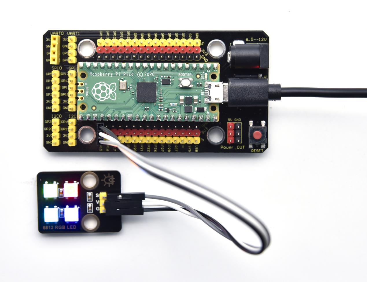
Project 58: Ultrasonic Radar
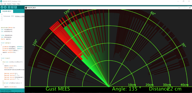
Description
We know that bats use echoes to determine the direction and the location of their preys. In real life, sonar is used to detect sounds in the water. Since the attenuation rate of electromagnetic waves in water is very high, it cannot be used to detect signals, however, the attenuation rate of sound waves in the water is much smaller, so sound waves are most commonly used underwater for observation and measurement.
In this experiment, we will use a speaker module, an RGB module and a 4-digit tube display to make a device for detection through ultrasonic.

Required Components
|
|
|
|---|---|---|
Raspberry Pi Pico Board*1 |
Raspberry Pi Pico Expansion Board*1 |
Keyes brick HC-SR04 Ultrasonic Sensor*1 |
|
|
|
Keyestudio Audio Power Amplifier*1 |
Keyestudio DIY Common Cathode RGB Module *1 |
Keyestudio DIY TM1650 4-Digit Segment Display*1 |
|
|
|
4P Dupont Wire*3 |
3P Dupont Wire*1 |
Micro USB Cable*1 |
Connection Diagram
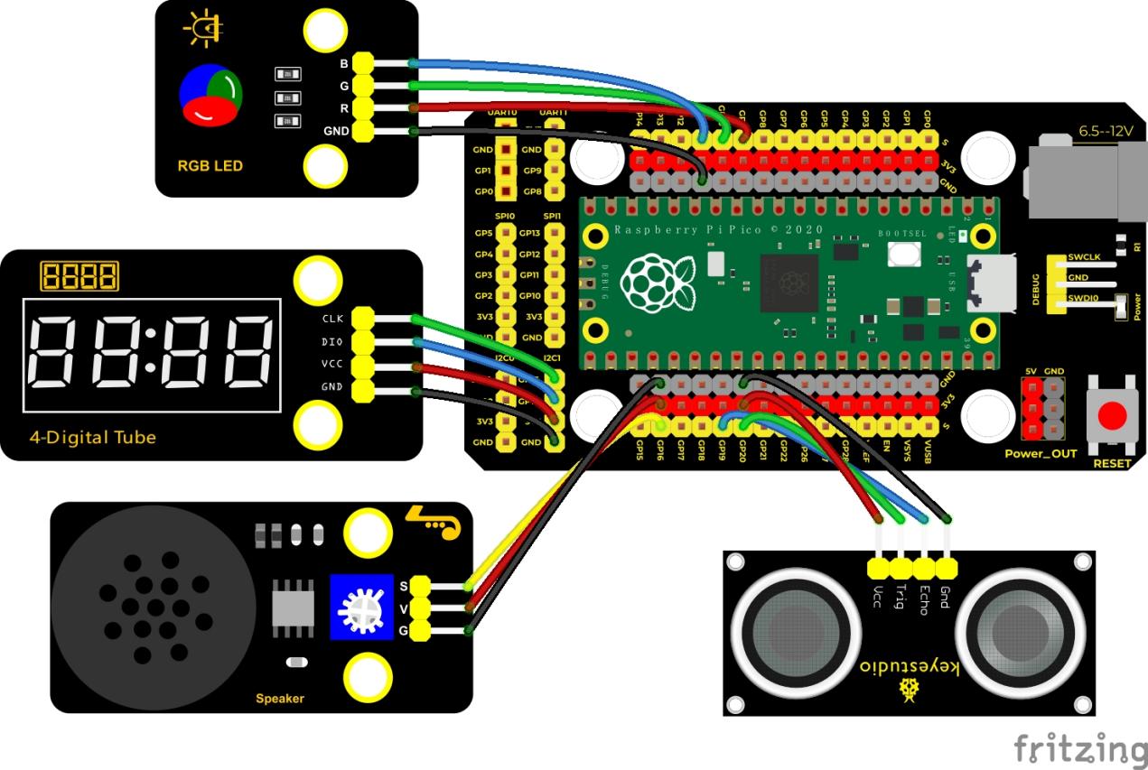
Run the test code
Double-click Ultrasonic radar.py, and clickto run the test code.
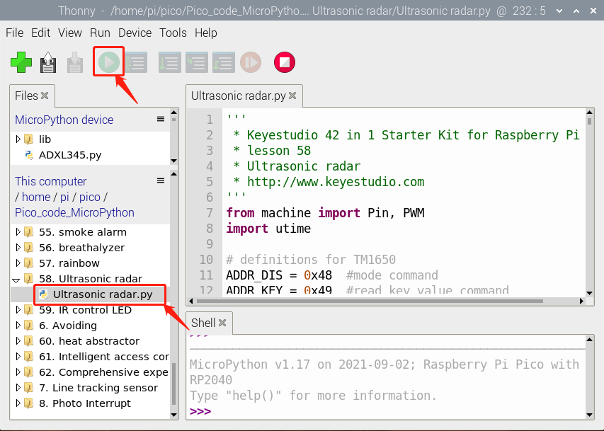
Test Code
'''
 * * Keyestudio 42 in 1 Starter Kit for Raspberry Pi Pico
 * lesson 58
 * Ultrasonic radar
 * http://www.keyestudio.com
'''
from machine import Pin, PWM
import utime

# definitions for TM1650
ADDR_DIS = 0x48  #mode command
ADDR_KEY = 0x49  #read key value command

# definitions for brightness
BRIGHT_DARKEST = 0
BRIGHT_TYPICAL = 2
BRIGHTEST      = 7

on  = 1
off = 0

# number:0~9
NUM = [0x3f,0x06,0x5b,0x4f,0x66,0x6d,0x7d,0x07,0x7f,0x6f]
# DIG = [0x68,0x6a,0x6c,0x6e]
DIG = [0x6e,0x6c,0x6a,0x68]
DOT = [0,0,0,0]

clkPin = 15
dioPin = 14
clk = machine.Pin(clkPin, machine.Pin.OUT)
dio = machine.Pin(dioPin, machine.Pin.OUT)

DisplayCommand = 0

def writeByte(wr_data):
    global clk,dio
    for i in range(8):
        if(wr_data & 0x80 == 0x80):
            dio.value(1)
        else:
            dio.value(0)
        clk.value(0)
        utime.sleep(0.0001)
        clk.value(1)
        utime.sleep(0.0001)
        clk.value(0)
        wr_data <<= 1
    return

def start():
    global clk,dio
    dio.value(1)
    clk.value(1)
    utime.sleep(0.0001)
    dio.value(0)
    return

def ack():
    global clk,dio
    dy = 0
    clk.value(0)
    utime.sleep(0.0001)
    dio = Pin(dioPin, machine.Pin.IN)
    while(dio.value() == 1):
        utime.sleep(0.0001)
        dy += 1
        if(dy>5000):
            break
    clk.value(1)
    utime.sleep(0.0001)
    clk.value(0)
    dio = Pin(dioPin, machine.Pin.OUT)
    return

def stop():
    global clk,dio
    dio.value(0)
    clk.value(1)
    utime.sleep(0.0001)
    dio.value(1)
    return

def displayBit(bit, num):
    global ADDR_DIS
    if(num > 9 and bit > 4):
        return
    start()
    writeByte(ADDR_DIS)
    ack()
    writeByte(DisplayCommand)
    ack()
    stop()
    start()
    writeByte(DIG[bit-1])
    ack()
    if(DOT[bit-1] == 1):
        writeByte(NUM[num] | 0x80)
    else:
        writeByte(NUM[num])
    ack()
    stop()
    return

def clearBit(bit):
    if(bit > 4):
        return
    start()
    writeByte(ADDR_DIS)
    ack()
    writeByte(DisplayCommand)
    ack()
    stop()
    start()
    writeByte(DIG[bit-1])
    ack()
    writeByte(0x00)
    ack()
    stop()
    return


def setBrightness(b = BRIGHT_TYPICAL):
    global DisplayCommand,brightness
    DisplayCommand = (DisplayCommand & 0x0f)+(b<<4)
    return

def setMode(segment = 0):
    global DisplayCommand
    DisplayCommand = (DisplayCommand & 0xf7)+(segment<<3)
    return

def displayOnOFF(OnOff = 1):
    global DisplayCommand
    DisplayCommand = (DisplayCommand & 0xfe)+OnOff
    return

def displayDot(bit, OnOff):
    if(bit > 4):
        return
    if(OnOff == 1):
        DOT[bit-1] = 1;
    else:
        DOT[bit-1] = 0;
    return

def InitDigitalTube():
    setBrightness(2)
    setMode(0)
    displayOnOFF(1)
    for _ in range(4):
        clearBit(_)
    return

def ShowNum(num): #0~9999
    displayBit(1,num%10)
    if(num < 10):
        clearBit(2)
        clearBit(3)
        clearBit(4)
    if(num > 9 and num < 100):
        displayBit(2,num//10%10)
        clearBit(3)
        clearBit(4)
    if(num > 99 and num < 1000):
        displayBit(2,num//10%10)
        displayBit(3,num//100%10)
        clearBit(4)
    if(num > 999 and num < 10000):
        displayBit(2,num//10%10)
        displayBit(3,num//100%10)
        displayBit(4,num//1000)

pwm_r = PWM(Pin(9))
pwm_g = PWM(Pin(10))
pwm_b = PWM(Pin(11))

pwm_r.freq(1000)
pwm_g.freq(1000)
pwm_b.freq(1000)

def light(red, green, blue):
    pwm_r.duty_u16(red)
    pwm_g.duty_u16(green)
    pwm_b.duty_u16(blue)

# ultrasonic ranging,unit: cm
def getDistance(trigger, echo):
    # produce 10us square waves
    trigger.low()   #preserve a short a low level to secure a high level:
    utime.sleep_us(2)
    trigger.high()
    utime.sleep_us(10)#pull up high levels, wait for 10ms and set low levels
    trigger.low()

    while echo.value() == 0: #build a while loop to detect pins are 0 or not, record the current time
        start = utime.ticks_us()
    while echo.value() == 1: #build a while loop to detect pins are 1 or not, record the current time
        end = utime.ticks_us()
    d = (end - start) * 0.0343 / 2 #travelling time x sound speed(343.2 m/s,0.0343cm for each ms),double distance is divided by 2
    return d

# set pins
trigger = Pin(20, Pin.OUT)
echo = Pin(19, Pin.IN)

buzzer = PWM(Pin(16))

def playtone(frequency):
    buzzer.duty_u16(1000)
    buzzer.freq(frequency)

def bequiet():
    buzzer.duty_u16(0)

# main program
InitDigitalTube()
while True:
    distance = int(getDistance(trigger, echo))
    ShowNum(distance)
    if distance <= 10:
        playtone(880)
        utime.sleep(0.1)
        bequiet()
        light(65535, 0, 0)
    elif distance <= 20:
        playtone(532)
        utime.sleep(0.2)
        bequiet()
        light(0, 0, 65535)
    else:
        light(0, 65535, 0)
Code Explanation
We set sound frequency and light color by adjusting different distance range.
We can adjust the distance range in the code.
Test Result
Wire up according to the connection diagram upload the run the code and power up. When the ultrasonic sensor detects different distances, the buzzer will produce different frequencies of sound, the RGB will show different colors, and the measured distances are displayed on the 4-digit tube display.
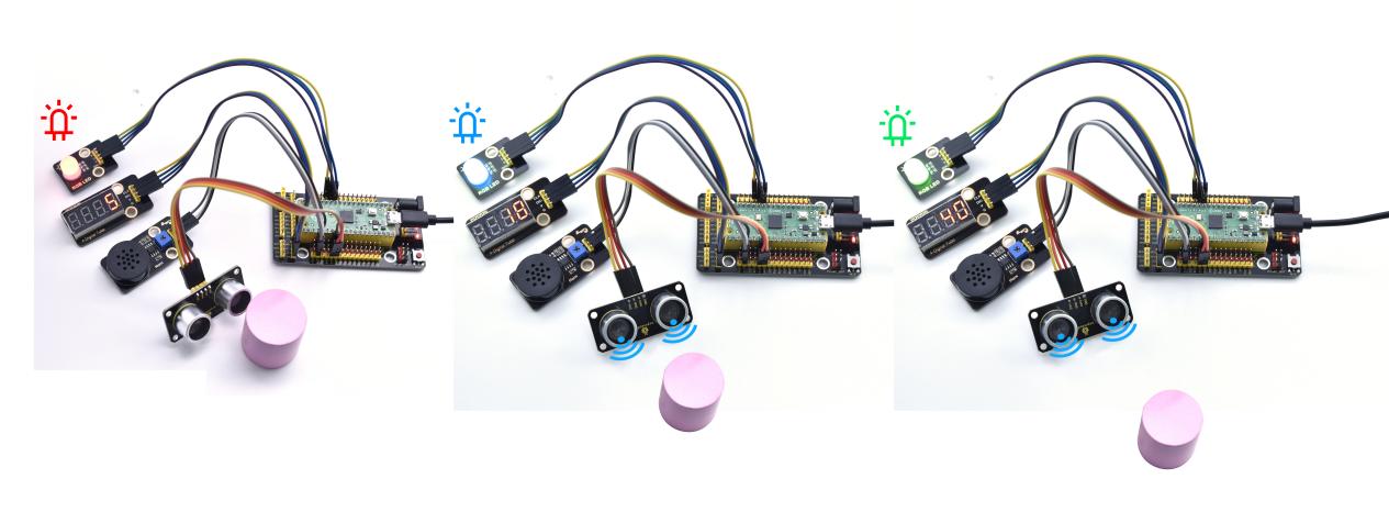
Project 59: IR Remote Control
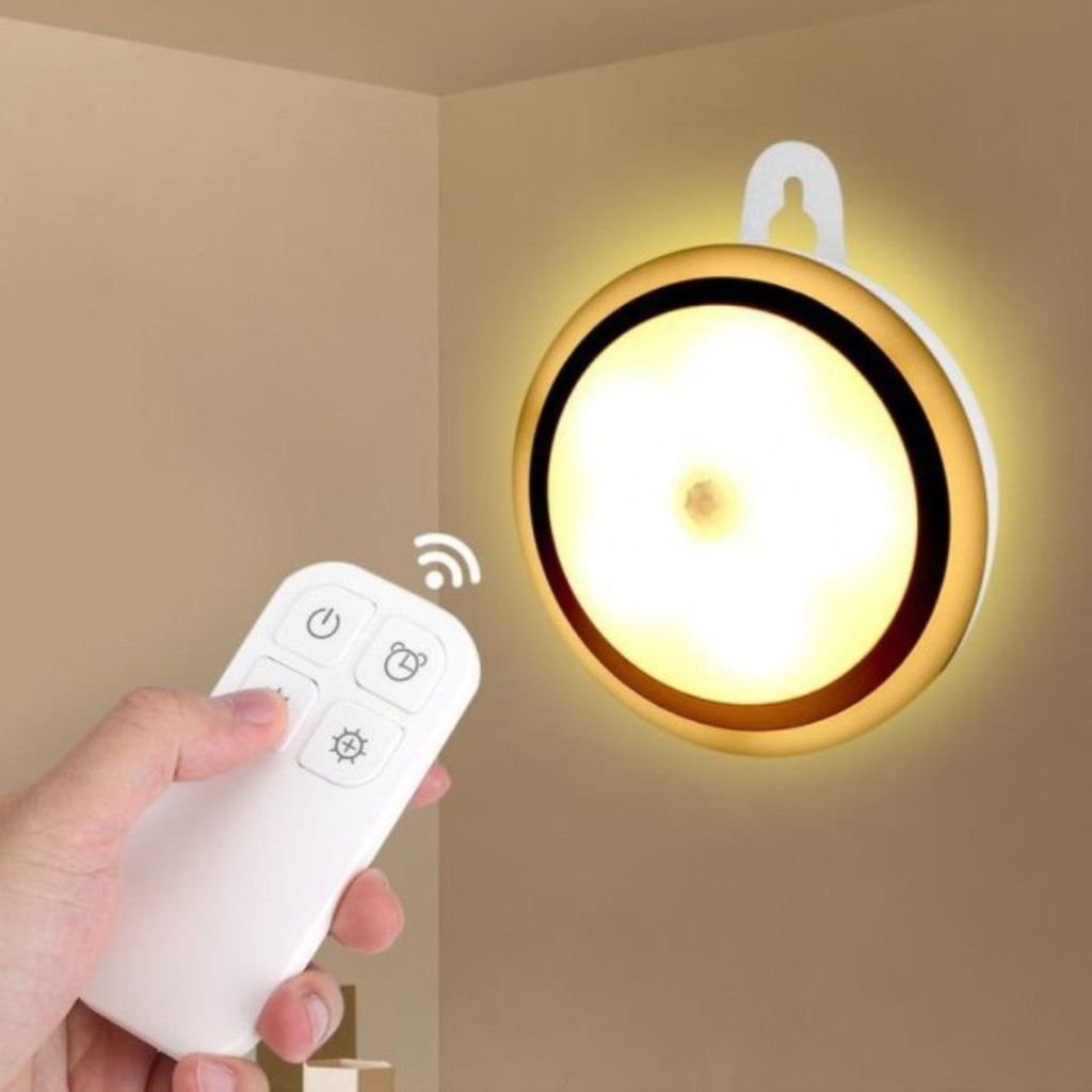
Introduction
In the previous experiments, we learned to turn on or turn off the LED, adjust the brightness of a light through PWM, and how to use the infrared receiver module. So in this experiment, we use an infrared remote control to control an LED module.
When we receive a value, we set the PWM value by the corresponding button value, thus you can adjust the brightness. Control the LED to turn on or turn off is in the same way. If we want to use the same button to control the LED to turn on or turn off, we can achieve it through the code.
Components
|
|
|
|
|---|---|---|---|
Raspberry Pi Pico Board*1 |
Raspberry Pi Pico Expansion Board*1 |
Keyestudio DIY Purple LED Module*1 |
Keyestudio DIY IR Receiver*1 |
|
|
|
|
Micro USB Cable*1 |
IR Remote Control*1 |
3P Dupont Wire*2 |
Connection Diagram
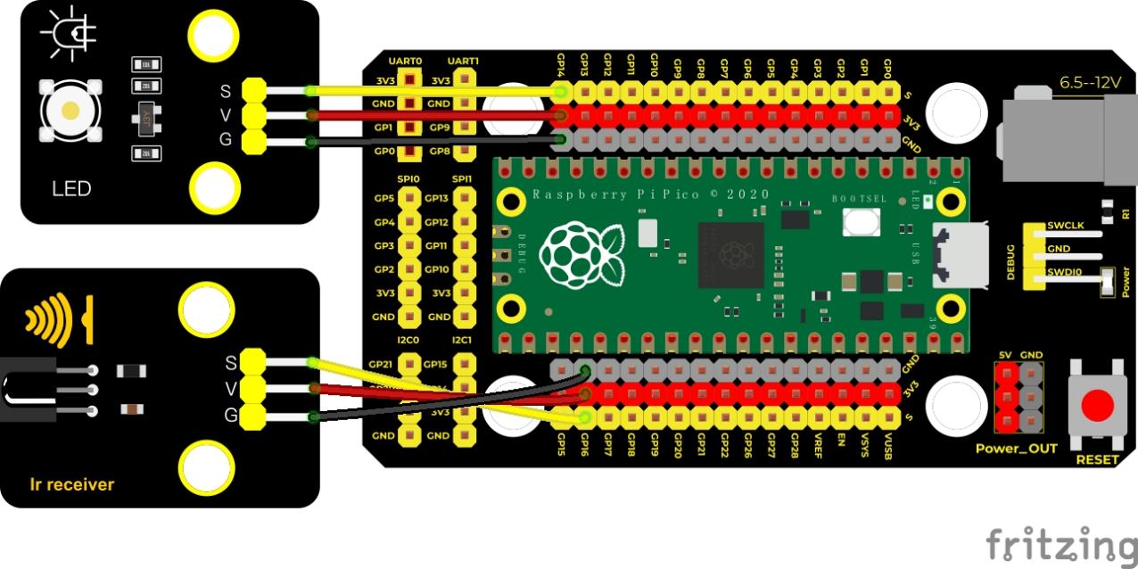
Run the test code
Double-click IR control LED.py,and clickto run the code.
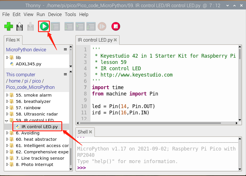
Test Code
'''
 * * Keyestudio 42 in 1 Starter Kit for Raspberry Pi Pico
 * lesson 59
 * IR control LED
 * http://www.keyestudio.com
'''
import time
from machine import Pin

led = Pin(14, Pin.OUT)
ird = Pin(16,Pin.IN)

act = {"1": "LLLLLLLLHHHHHHHHLHHLHLLLHLLHLHHH","2": "LLLLLLLLHHHHHHHHHLLHHLLLLHHLLHHH","3": "LLLLLLLLHHHHHHHHHLHHLLLLLHLLHHHH",
       "4": "LLLLLLLLHHHHHHHHLLHHLLLLHHLLHHHH","5": "LLLLLLLLHHHHHHHHLLLHHLLLHHHLLHHH","6": "LLLLLLLLHHHHHHHHLHHHHLHLHLLLLHLH",
       "7": "LLLLLLLLHHHHHHHHLLLHLLLLHHHLHHHH","8": "LLLLLLLLHHHHHHHHLLHHHLLLHHLLLHHH","9": "LLLLLLLLHHHHHHHHLHLHHLHLHLHLLHLH",
       "0": "LLLLLLLLHHHHHHHHLHLLHLHLHLHHLHLH","Up": "LLLLLLLLHHHHHHHHLHHLLLHLHLLHHHLH","Down": "LLLLLLLLHHHHHHHHHLHLHLLLLHLHLHHH",
       "Left": "LLLLLLLLHHHHHHHHLLHLLLHLHHLHHHLH","Right": "LLLLLLLLHHHHHHHHHHLLLLHLLLHHHHLH","Ok": "LLLLLLLLHHHHHHHHLLLLLLHLHHHHHHLH",
       "*": "LLLLLLLLHHHHHHHHLHLLLLHLHLHHHHLH","#": "LLLLLLLLHHHHHHHHLHLHLLHLHLHLHHLH"}

def read_ircode(ird):
    wait = 1
    complete = 0
    seq0 = []
    seq1 = []

    while wait == 1:
        if ird.value() == 0:
            wait = 0
    while wait == 0 and complete == 0:
        start = time.ticks_us()
        while ird.value() == 0:
            ms1 = time.ticks_us()
        diff = time.ticks_diff(ms1,start)
        seq0.append(diff)
        while ird.value() == 1 and complete == 0:
            ms2 = time.ticks_us()
            diff = time.ticks_diff(ms2,ms1)
            if diff > 10000:
                complete = 1
        seq1.append(diff)

    code = ""
    for val in seq1:
        if val < 2000:
            if val < 700:
                code += "L"
            else:
                code += "H"
    # print(code)
    command = ""
    for k,v in act.items():
        if code == v:
            command = k
    if command == "":
        command = code
    return command

flag = False
while True:
#     global flag
    command = read_ircode(ird)
    print(command, end = "  ")
    print(flag, end = "  ")
    if command == "Ok":
        if flag == True:
            led.value(1)
            flag = False
            print("led on")
        else:
            led.value(0)
            flag = True
            print("led off")
    time.sleep(0.1)
Code Explanation
1. We define a boolean variable. There are two boolean variables. true (true) or false (false), boolean flag = true.
2. When we press the OK button, the value of infrared reception is 64. At this time, we need to set a boolean variable flag. When the flag is true (true), the LED is turned on, and when it is false (false), the LED is turned off and turned on. After the LED is on and set it to false. We press the OK key, the LED will be off.
Test Result
Wire up, upload the test code and open the Shell monitor. Press the OK button of the remote, the LED will be on; press it again, the LED will be off.
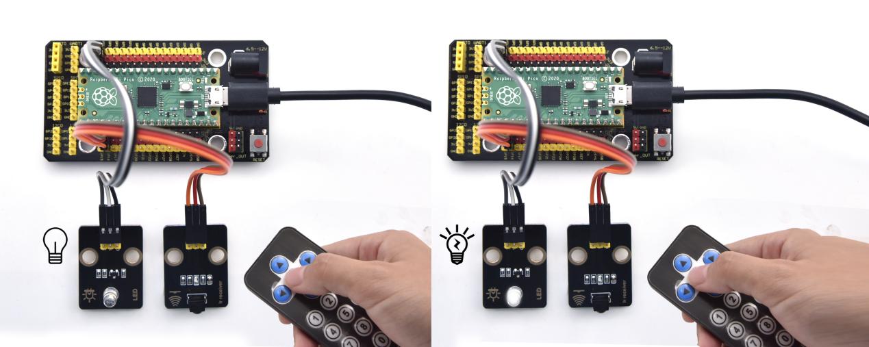
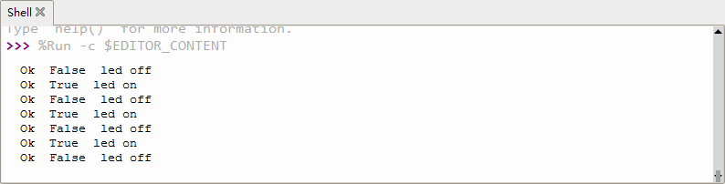
Project 60: Heat Dissipation Device

Description
We will use a temperature sensor and some modules to make a smart cooling device in this experiment. When the ambient temperature is higher than a certain value, the motor is turned on, thereby reducing the ambient temperature and achieving the heat dissipation effect. Then display the temperature value in the four-digit segment display.
Required Components
|
|
|
|
|---|---|---|---|
Raspberry Pi Pico Board*1 |
Raspberry Pi Pico Expansion Board*1 |
keyestudio 130 Motor*1 |
Keyestudio TM1650 4-Digit Segment Display*1 |
|
|
|
|
Keyestudio 18B20 Temperature Sensor*1 |
3P Dupont Wire*1 |
4P Dupont Wire*2 |
Micro USB Cable*1 |
Connection Diagram
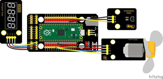
Run the test code
Find and double-click heat_abstractor.py and click.
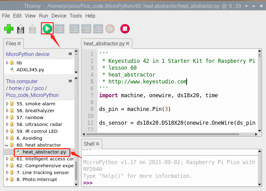
Test Code
'''
 * * Keyestudio 42 in 1 Starter Kit for Raspberry Pi Pico
 * lesson 60
 * heat_abstractor
 * http://www.keyestudio.com
'''
import machine, onewire, ds18x20, time

ds_pin = machine.Pin(3)

ds_sensor = ds18x20.DS18X20(onewire.OneWire(ds_pin))

roms = ds_sensor.scan()

#two pins of the motor
INA = machine.Pin(20, machine.Pin.OUT)
INB = machine.Pin(21, machine.Pin.OUT)
# definitions for TM1650
ADDR_DIS = 0x48  #mode command
ADDR_KEY = 0x49  #read key value command

# definitions for brightness
BRIGHT_DARKEST = 0
BRIGHT_TYPICAL = 2
BRIGHTEST      = 7

on  = 1
off = 0

# number:0~9
NUM = [0x3f,0x06,0x5b,0x4f,0x66,0x6d,0x7d,0x07,0x7f,0x6f]
# DIG = [0x68,0x6a,0x6c,0x6e]
DIG = [0x6e,0x6c,0x6a,0x68]
DOT = [0,0,0,0]

clkPin = 15
dioPin = 14
clk = machine.Pin(clkPin, machine.Pin.OUT)
dio = machine.Pin(dioPin, machine.Pin.OUT)

DisplayCommand = 0

def writeByte(wr_data):
    global clk,dio
    for i in range(8):
        if(wr_data & 0x80 == 0x80):
            dio.value(1)
        else:
            dio.value(0)
        clk.value(0)
        time.sleep(0.0001)
        clk.value(1)
        time.sleep(0.0001)
        clk.value(0)
        wr_data <<= 1
    return

def start():
    global clk,dio
    dio.value(1)
    clk.value(1)
    time.sleep(0.0001)
    dio.value(0)
    return

def ack():
    global clk,dio
    dy = 0
    clk.value(0)
    time.sleep(0.0001)
    dio = machine.Pin(dioPin, machine.Pin.IN)
    while(dio.value() == 1):
        time.sleep(0.0001)
        dy += 1
        if(dy>5000):
            break
    clk.value(1)
    time.sleep(0.0001)
    clk.value(0)
    dio = machine.Pin(dioPin, machine.Pin.OUT)
    return

def stop():
    global clk,dio
    dio.value(0)
    clk.value(1)
    time.sleep(0.0001)
    dio.value(1)
    return

def displayBit(bit, num):
    global ADDR_DIS
    if(num > 9 and bit > 4):
        return
    start()
    writeByte(ADDR_DIS)
    ack()
    writeByte(DisplayCommand)
    ack()
    stop()
    start()
    writeByte(DIG[bit-1])
    ack()
    if(DOT[bit-1] == 1):
        writeByte(NUM[num] | 0x80)
    else:
        writeByte(NUM[num])
    ack()
    stop()
    return

def clearBit(bit):
    if(bit > 4):
        return
    start()
    writeByte(ADDR_DIS)
    ack()
    writeByte(DisplayCommand)
    ack()
    stop()
    start()
    writeByte(DIG[bit-1])
    ack()
    writeByte(0x00)
    ack()
    stop()
    return


def setBrightness(b = BRIGHT_TYPICAL):
    global DisplayCommand,brightness
    DisplayCommand = (DisplayCommand & 0x0f)+(b<<4)
    return

def setMode(segment = 0):
    global DisplayCommand
    DisplayCommand = (DisplayCommand & 0xf7)+(segment<<3)
    return

def displayOnOFF(OnOff = 1):
    global DisplayCommand
    DisplayCommand = (DisplayCommand & 0xfe)+OnOff
    return

def displayDot(bit, OnOff):
    if(bit > 4):
        return
    if(OnOff == 1):
        DOT[bit-1] = 1;
    else:
        DOT[bit-1] = 0;
    return

def InitDigitalTube():
    setBrightness(2)
    setMode(0)
    displayOnOFF(1)
    for _ in range(4):
        clearBit(_)
    return

def ShowNum(num): #0~9999
    displayBit(1,num%10)
    if(num < 10):
        clearBit(2)
        clearBit(3)
        clearBit(4)
    if(num > 9 and num < 100):
        displayBit(2,num//10%10)
        clearBit(3)
        clearBit(4)
    if(num > 99 and num < 1000):
        displayBit(2,num//10%10)
        displayBit(3,num//100%10)
        clearBit(4)
    if(num > 999 and num < 10000):
        displayBit(2,num//10%10)
        displayBit(3,num//100%10)
        displayBit(4,num//1000)

InitDigitalTube()
print('Found DS devices: ', roms)

while True:
    ds_sensor.convert_temp()
    time.sleep_ms(750)
    for rom in roms:
        value = ds_sensor.read_temp(rom)
        print(value)
        ShowNum(int(value))
        if value > 28:
            INA.value(0)
            INB.value(1)
        else:
            INA.value(0)
            INB.value(0)
Code Explanation
The setting of variables and the storage of detection values are the same as what we learned earlier. We also set a temperature threshold and control the rotation of the motor when the threshold is exceeded, and then we use the digital tube to display the temperature value.
Test Result
Wire up and run the test code. We can see the temperature of the current environment (unit is Celsius) on the four-digit segment display, as shown in the figure below. If this value exceeds the value we set, the fan will rotate to dissipate heat.
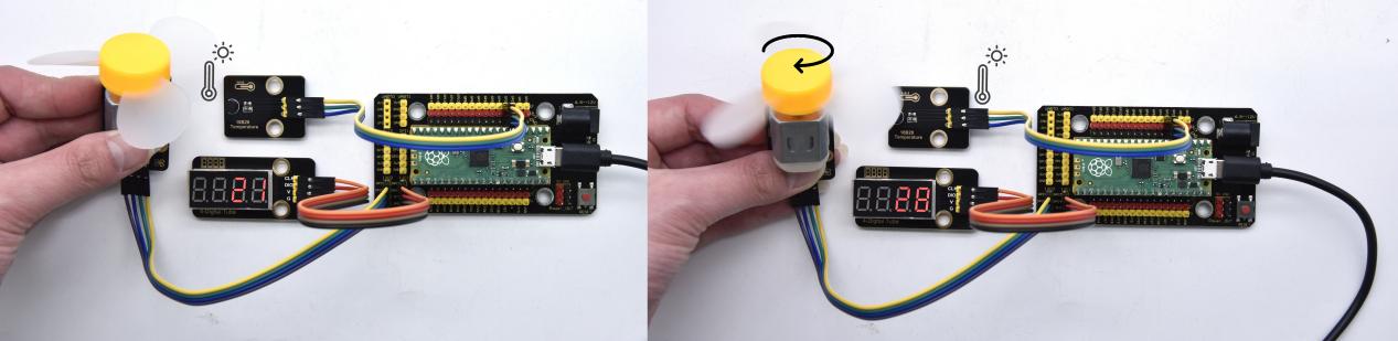
Project 61: Intelligent Entrance Guard System

Description
In this project, we use the RFID522 card swiping module and the servo to set up an intelligent access control system. The principle is very simple. We use RFID522 swipe card module, an IC card or key card to unlock.
Required Components
|
|
|
|
|---|---|---|---|
Raspberry Pi Pico Board*1 |
Raspberry Pi Pico Expansion Board*1 |
Key*1 |
IC Card*1 |
|
|
|
|
Keyestudio RFID Module*1 |
Servo*1 |
4P Dupont Wire*1 |
Micro USB Cable*1 |
Connection Diagram
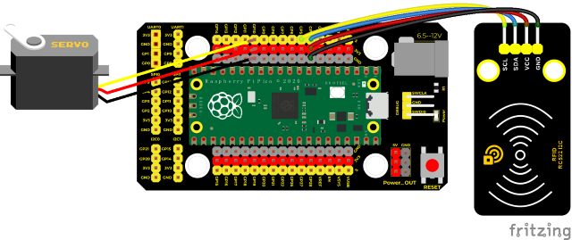
Run the code
Find Intelligent access control.py and double-click it and clickto run the code.
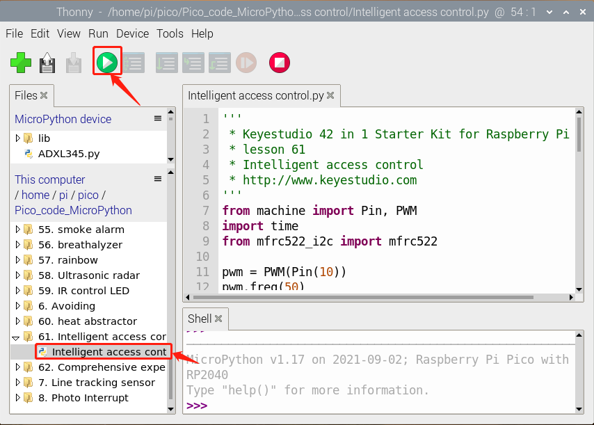
Test Code
'''
 * Keyes 42 in 1 Starter Kit for Raspberry Pi Pico
 * lesson 61
 * Intelligent access control
'''
from machine import Pin, PWM
import time
from mfrc522_i2c import mfrc522

pwm = PWM(Pin(10))
pwm.freq(50)

'''
The duty cycle corresponding to the angle
0°----2.5%----1638
45°----5%----3276
90°----7.5%----4915
135°----10%----6553
180°----12.5%----8192
'''
angle_0 = 1638
angle_90 = 4915
angle_180 = 8192

#i2c config
addr = 0x28
scl = 5
sda = 4

rc522 = mfrc522(scl, sda, addr)
rc522.PCD_Init()
rc522.ShowReaderDetails()            # Show details of PCD - MFRC522 Card Reader details

uid1 = [204, 229, 73, 100]
uid2 = [148, 232, 198, 91]

pwm.duty_u16(angle_180)
time.sleep(1)

while True:
    if rc522.PICC_IsNewCardPresent():
        #print("Is new card present!")
        if rc522.PICC_ReadCardSerial() == True:
            print("Card UID:", end=' ')
            print(rc522.uid.uidByte[0 : rc522.uid.size])
            if rc522.uid.uidByte[0 : rc522.uid.size] == uid1 or rc522.uid.uidByte[0 : rc522.uid.size] == uid2:
                pwm.duty_u16(angle_0)
        time.sleep(5)
    else :
        pwm.duty_u16(angle_180)
Code Explanation
In the previous experiment, our card swipe module has tested the information of IC card and key. Then we use this corresponding information to control the door.
Test Result
Upload the test code, wire up and power up with a USB cable, open the shell and set the baud rate to 9600; the shell displays information.
When we use the IC card or blue key to swipe the card, the shell displays the card information and “open the door”, as shown in the figure below, the servo rotates to the corresponding angle to simulate opening the door.
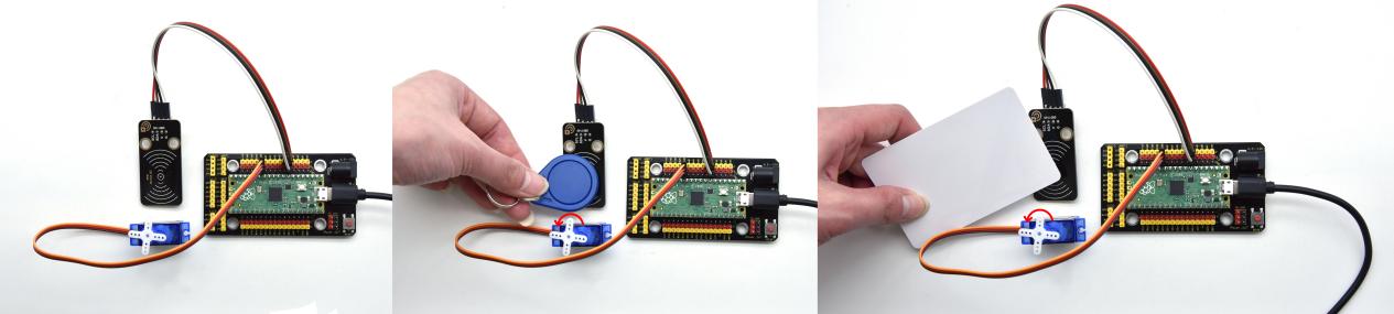
Project 62: Comprehensive Experiment

Introduction
We did a lot of experiments, and for each one we needed to re-upload the code, so can we achieve different functions through an experiment?
In this experiment, we will use an external button module to achieve different functions.
Components Required
|
|
|
|---|---|---|
Raspberry Pi Pico Board*1 |
Raspberry Pi Pico Expansion Board*1 |
Keyestudio DIY Purple LED Module*1 |
|
|
|
Keyestudio Button Module*1 |
Keyestudio Rotary Encoder*1 |
Keyestudio Obstacle Avoidance Sensor*1 |
|
|
|
Keyestudio IR Receiver*1 |
Keyestudio DIY Joystick Module*1 |
keyes brick HC-SR04 Ultrasonic sensor *1 |
|
|
|
Keyestudio DIY Common Cathode RGB Module *1 |
Keyestudio XHT11 Temperature and Humidity Sensor *1 |
Keyestudio ADXL345 Acceleration Sensor*1 |
|
|
|
3P Dupont Wire*6 |
4P Dupont Wire*3 |
5P Dupont Wire*1 |
|
|
|
Micro USB Cable*1 |
Remote Control*1 |
Connection Diagram
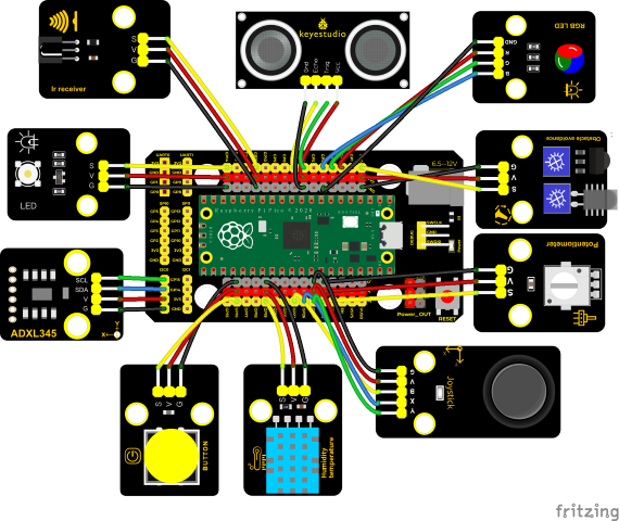
Run the test code
Find the Comprehensive experiment.py, double-click the code and click
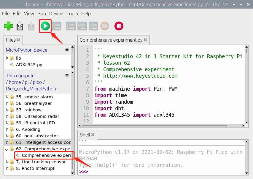
Test Code
'''
 * Keyestudio 42 in 1 Starter Kit for Raspberry Pi Pico
 * lesson 62
 * Comprehensive experiment
 * http://www.keyestudio.com
'''
from machine import Pin, PWM
import time
import random
import dht
from ADXL345 import adxl345

scl = Pin(21)
sda = Pin(20)
bus = 0
snsr = adxl345(bus, scl, sda)

pwm_r = PWM(Pin(2))
pwm_g = PWM(Pin(3))
pwm_b = PWM(Pin(4))

pwm_r.freq(1000)
pwm_g.freq(1000)
pwm_b.freq(1000)

pin = machine.Pin(19, machine.Pin.OUT, machine.Pin.PULL_DOWN)
xht = dht.DHT11(pin)

potentiometer = machine.ADC(28)
button = Pin(16, Pin.IN)
led = PWM(Pin(14))
led.freq(1000)
ird = Pin(11,Pin.IN)
B = machine.Pin(22, machine.Pin.IN)
X = machine.ADC(26)
Y = machine.ADC(27)
avoid = Pin(0, Pin.IN)
# Set Ultrasonic Pins
trigger = Pin(6, Pin.OUT)
echo = Pin(7, Pin.IN)

def light(red, green, blue):
    pwm_r.duty_u16(red)
    pwm_g.duty_u16(green)
    pwm_b.duty_u16(blue)

act = {"1": "LLLLLLLLHHHHHHHHLHHLHLLLHLLHLHHH","2": "LLLLLLLLHHHHHHHHHLLHHLLLLHHLLHHH","3": "LLLLLLLLHHHHHHHHHLHHLLLLLHLLHHHH",
       "4": "LLLLLLLLHHHHHHHHLLHHLLLLHHLLHHHH","5": "LLLLLLLLHHHHHHHHLLLHHLLLHHHLLHHH","6": "LLLLLLLLHHHHHHHHLHHHHLHLHLLLLHLH",
       "7": "LLLLLLLLHHHHHHHHLLLHLLLLHHHLHHHH","8": "LLLLLLLLHHHHHHHHLLHHHLLLHHLLLHHH","9": "LLLLLLLLHHHHHHHHLHLHHLHLHLHLLHLH",
       "0": "LLLLLLLLHHHHHHHHLHLLHLHLHLHHLHLH","Up": "LLLLLLLLHHHHHHHHLHHLLLHLHLLHHHLH","Down": "LLLLLLLLHHHHHHHHHLHLHLLLLHLHLHHH",
       "Left": "LLLLLLLLHHHHHHHHLLHLLLHLHHLHHHLH","Right": "LLLLLLLLHHHHHHHHHHLLLLHLLLHHHHLH","Ok": "LLLLLLLLHHHHHHHHLLLLLLHLHHHHHHLH",
       "*": "LLLLLLLLHHHHHHHHLHLLLLHLHLHHHHLH","#": "LLLLLLLLHHHHHHHHLHLHLLHLHLHLHHLH"}

def read_ircode(ird):
    wait = 1
    complete = 0
    seq0 = []
    seq1 = []

    while wait == 1:
        if ird.value() == 0:
            wait = 0
    while wait == 0 and complete == 0:
        start = time.ticks_us()
        while ird.value() == 0:
            ms1 = time.ticks_us()
        diff = time.ticks_diff(ms1,start)
        seq0.append(diff)
        while ird.value() == 1 and complete == 0:
            ms2 = time.ticks_us()
            diff = time.ticks_diff(ms2,ms1)
            if diff > 10000:
                complete = 1
        seq1.append(diff)

    code = ""
    for val in seq1:
        if val < 2000:
            if val < 700:
                code += "L"
            else:
                code += "H"
    # print(code)
    command = ""
    for k,v in act.items():
        if code == v:
            command = k
    if command == "":
        command = code
    return command


# ultrasonic ranging,unit: cm
def getDistance(trigger, echo):
    # produce 10us square waves
    trigger.low()   #preserve a short a low level to secure a high level:    time.sleep_us(2)
    trigger.high()
    time.sleep_us(10)#pull up high levels, wait for 10ms and set low levels
    trigger.low()

    while echo.value() == 0: #Create a while loop to detect whether the echo pin is 0, and record the current time
        start = time.ticks_us()
    while echo.value() == 1: #build a while loop to detect pins are 0 or not, record the current time
        end = time.ticks_us()
    d = (end - start) * 0.0343 / 2 #travelling time x sound speed(343.2 m/s,0.0343cm for each ms),double distance is divided by 2
    return d


keys = 0
nums = 0
print(keys % 8)
def toggle_handle(pin):
    global keys
    keys += 1
    print(keys % 7)

button.irq(trigger = Pin.IRQ_FALLING, handler = toggle_handle)

def showRGB():
    R = random.randint(0,65535)
    G = random.randint(0,65535)
    B = random.randint(0,65535)
    light(R, G, B)
    time.sleep(0.3)

def showxht11():
    print("temperature:{} ℃  humidity:{} %".format(xht.temperature, xht.humidity))
    time.sleep(1)

def IRreceive():
    command = read_ircode(ird)
    print(command)

def showJoystick():
    B_value = B.value()
    X_value = X.read_u16()
    Y_value = Y.read_u16()
    print("button:", end = " ")
    print(B_value, end = " ")
    print("X:", end = " ")
    print(X_value, end = " ")
    print("Y:", end = " ")
    print(Y_value)
    time.sleep(0.1)

def adjustLight():
    pot_value = potentiometer.read_u16()
    print(pot_value)
    led.duty_u16(pot_value)
    time.sleep(0.1)

def showAvoid():
    if avoid.value() == 0:
        print("There are obstacles")
    else:
        print("All going well")
    time.sleep(0.1)

def showDistance():
    distance = getDistance(trigger, echo)
    print("The distance is :{:.2f} cm".format(distance))
    time.sleep(0.1)

def showADXL345():
    x,y,z = snsr.readXYZ()
    print('x:',x,'y:',y,'z:',z,'uint:mg')
    time.sleep(0.1)

while True:
    nums = keys % 8  #remainder is 0 1 2 3 4 5 6 and 7
    if nums == 0:  #Display RGB
        showRGB()
    elif nums == 1:  #Displays the value of infrared reception
        IRreceive()
    elif nums == 2:  #Display temperature and humidity
        showxht11()
    elif nums == 3:  #Display joystick value
        showJoystick()
    elif nums == 4:  #potentiometer to adjust led
        adjustLight()
    elif nums == 5:  #Display obstacle information
        showAvoid()
    elif nums == 6:  #Display ultrasonic ranging value
        showDistance()
    elif nums == 7:  #Display ultrasonic ranging value
        showADXL345()
Code Explanation
1. Calculate how many times the button is pressed, divide it by 8, and get the remainder which is 0, 1 2, 3, 4, 5 , 6 and 7. According to different remainders, construct five unique functions to control the experiment and realize different functions.
2. We add dht and adxl345 library files in this project.
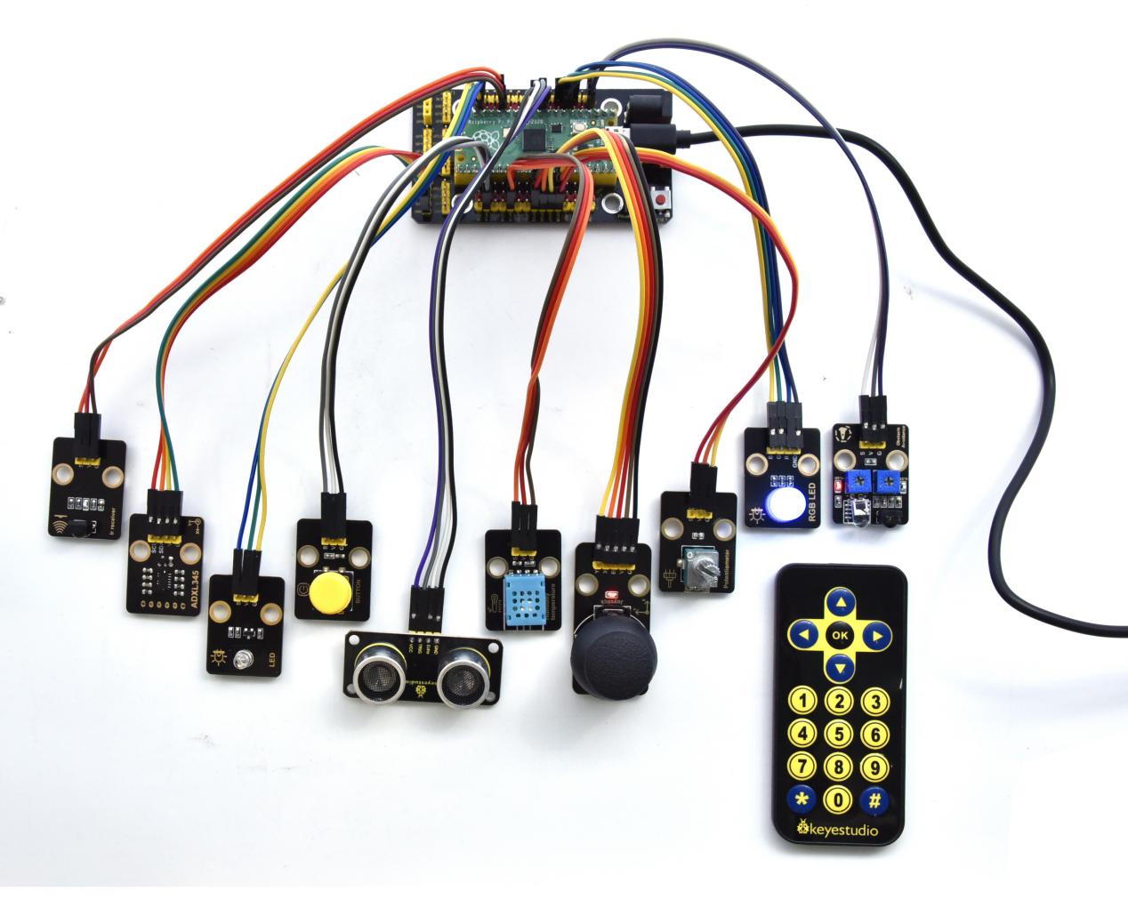
Test Result
Connect the wires according to the wiring diagram, use the USB to power on, and run the test code. At the beginning, the number of keys is 0, the remainder is 0, and the four lamp beads on the RGB module flash with random colors.
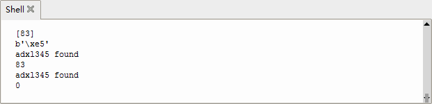
Press the button, the RGB stops flashing, press once, the remainder is 1. If we point at IR receiver with the infrared remote control and press the button,the serial monitor will display as follows.
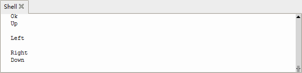
Press a key twice, the time of pressing buttons is 2 and the remainder is 2. Read temperature and humidity values. As shown below:
Note: we need to press any a key, because the IR reception function waits for signals.
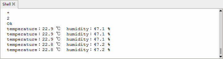
Press a key again, the time of pressing buttons is 3 and the remainder is 3. Read digital values at x, y and z axis of the joystick module. As shown below:
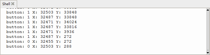
Press the key for the fourth time, the remainder is 4. Then the potentiometer can adjust the PWM value at the GP14 port to control LED brightness of the purple LED.
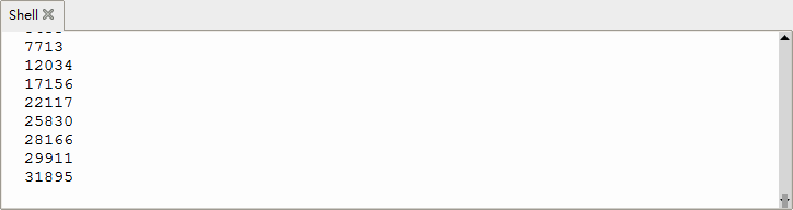
Press the key for the fifth time, the remainder is 5. Then the obstacle avoidance sensor can detect obstacles, as shown below:
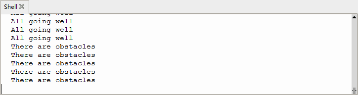
Press the key for the sixth time, the remainder is 6. Then the ultrasonic sensor can detect distance away from obstacles, as shown below:
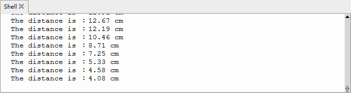
Press the key for seventh time and the remainder is 7. The shell will print out the acceleration value.
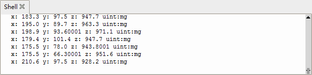
Press the key for eighth time and the remainder is 0. Then the RGB will flash. If you press keys incessantly, remainders will change in loop way. So does functions.